AD625JNZ Analog Devices Inc, AD625JNZ Datasheet - Page 10
AD625JNZ
Manufacturer Part Number
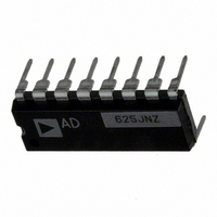
AD625JNZ
Description
IC AMP INST 25MHZ LN 16DIP
Manufacturer
Analog Devices Inc
Type
Low Noiser
Specifications of AD625JNZ
Amplifier Type
Instrumentation
Number Of Circuits
1
Slew Rate
5 V/µs
Gain Bandwidth Product
25MHz
-3db Bandwidth
650kHz
Current - Input Bias
30nA
Voltage - Input Offset
50µV
Current - Supply
3.5mA
Voltage - Supply, Single/dual (±)
±6 V ~ 18 V
Operating Temperature
0°C ~ 70°C
Mounting Type
Through Hole
Package / Case
16-DIP (0.300", 7.62mm)
Bandwidth
650 kHz
Common Mode Rejection Ratio
75
Current, Input Bias
±30 nA
Current, Input Offset
±2 nA
Current, Output
5 mA
Current, Supply
3.5 mA
Number Of Amplifiers
Five
Package Type
PDIP-16
Power Dissipation
450 mW
Resistance, Input
1 Gigaohms
Temperature, Operating, Range
0 to +70 °C
Voltage, Input Offset
50 μV
Voltage, Noise
4 nV/sqrt Hz
Voltage, Output Swing
±10 V
Voltage, Supply
±6 to ±18 V
No. Of Amplifiers
5
Input Offset Voltage
200µV
Gain Db Min
1dB
Amplifier Output
Single Ended
Cmrr
115dB
Supply Voltage Range
± 6V To ± 18V
Rohs Compliant
Yes
Lead Free Status / RoHS Status
Lead free / RoHS Compliant
Output Type
-
Current - Output / Channel
-
Lead Free Status / Rohs Status
RoHS Compliant part
Electrostatic Device
Available stocks
Company
Part Number
Manufacturer
Quantity
Price


AD625
the I × R drops “inside the loop” and virtually eliminating this
error source.
Typically, IC instrumentation amplifiers are rated for a full ± 10
volt output swing into 2 kΩ. In some applications, however, the
need exists to drive more current into heavier loads. Figure 29
shows how a high-current booster may be connected “inside the
loop” of an instrumentation amplifier. By using an external
power boosting circuit, the power dissipated by the AD625 will
remain low, thereby, minimizing the errors induced by self-
heating. The effects of nonlinearities, offset and gain inaccura-
cies of the buffer are reduced by the loop gain of the AD625’s
output amplifier.
REFERENCE TERMINAL
The reference terminal may be used to offset the output by up
to ± 10 V. This is useful when the load is “floating” or does not
share a ground with the rest of the system. It also provides a
direct means of injecting a precise offset. However, it must be
remembered that the total output swing is ± 10 volts, from
ground, to be shared between signal and reference offset.
The AD625 reference terminal must be presented with nearly
zero impedance. Any significant resistance, including those
caused by PC layouts or other connection techniques, will in-
crease the gain of the noninverting signal path, thereby, upset-
ting the common-mode rejection of the in-amp. Inadvertent
thermocouple connections created in the sense and reference
lines should also be avoided as they will directly affect the out-
put offset voltage and output offset voltage drift.
In the AD625 a reference source resistance will unbalance the
CMR trim by the ratio of 10 kΩ/R
ence source impedance is 1 Ω, CMR will be reduced to 80 dB
(10 kΩ/1 Ω = 80 dB). An operational amplifier may be used to
provide the low impedance reference point as shown in Figure
30. The input offset voltage characteristics of that amplifier will
add directly to the output offset voltage performance of the
instrumentation amplifier.
The circuit of Figure 30 also shows a CMOS DAC operating in
the bipolar mode and connected to the reference terminal to
provide software controllable offset adjustments. The total offset
range is equal to ± (V
cal about 0 V R3 = 2 × R4.
The offset per bit is equal to the total offset range divided by 2
where N = number of bits of the DAC. The range of offset for
Figure 30 is ± 120 mV, and the offset is incremented in steps of
0.9375 mV/LSB.
V
V
IN
IN
+
–
R
R
R
G
F
F
REF
/2 × R5/R4), however, to be symmetri-
AD625
–V
+V
S
S
REF
. For example, if the refer-
REFERENCE
SENSE
X1
R
I
N
,
An instrumentation amplifier can be turned into a voltage-to-
current converter by taking advantage of the sense and reference
terminals as shown in Figure 31.
By establishing a reference at the “low” side of a current setting
resistor, an output current may be defined as a function of input
voltage, gain and the value of that resistor. Since only a small
current is demanded at the input of the buffer amplifier A1, the
forced current I
drift specifications of A2 must be added to the output offset and
drift specifications of the In-Amp.
INPUT AND OUTPUT OFFSET VOLTAGE
Offset voltage specifications are often considered a figure of
merit for instrumentation amplifiers. While initial offset may be
adjusted to zero, shifts in offset voltage due to temperature
variations will cause errors. Intelligent systems can often correct
for this factor with an autozero cycle, but this requires extra
circuitry.
INPUTS
DATA
V
AD589
S
MSB
LSB
39k
WR
CS
E
A
A
N
0
1
1.2V
GND V
AD7502
V
V
IN
IN
L
DD
+
–
R
R
R
8-BIT DAC
will largely flow through the load. Offset and
G
V
AD7524
F
F
SS
+V
S
AD625
R
FB
+IN
–IN
V
C
REF
OUT 1
OUT 2
1
SENSE
AD625
+V
–V
S
S
1/2
+V
AD711
AD712
S
+V
R1
X
–
LOAD
SENSE
10k
20k
R4
I
R3
L
5k
REFERENCE
V
OUT
0.01 F
1/2
2k
–V
R5
S
AD712
Related parts for AD625JNZ
Image
Part Number
Description
Manufacturer
Datasheet
Request
R

Part Number:
Description:
±1.7g Dual-Axis IMEMS Accelerometer Evaluation Board
Manufacturer:
Analog Devices Inc
Datasheet:

Part Number:
Description:
Inertial Sensor Evaluation System
Manufacturer:
Analog Devices Inc
Datasheet:
Part Number:
Description:
Manufacturer:
Analog Devices Inc
Datasheet:
Part Number:
Description:
Manufacturer:
Analog Devices Inc
Datasheet:
Part Number:
Description:
Manufacturer:
Analog Devices Inc
Datasheet:
Part Number:
Description:
Manufacturer:
Analog Devices Inc
Datasheet:
Part Number:
Description:
Manufacturer:
Analog Devices Inc
Datasheet:
Part Number:
Description:
Manufacturer:
Analog Devices Inc
Datasheet:
Part Number:
Description:
Manufacturer:
Analog Devices Inc
Datasheet:
Part Number:
Description:
Manufacturer:
Analog Devices Inc
Datasheet:
Part Number:
Description:
Manufacturer:
Analog Devices Inc
Datasheet:
Part Number:
Description:
Manufacturer:
Analog Devices Inc
Datasheet:
Part Number:
Description:
Manufacturer:
Analog Devices Inc
Datasheet: