AD625JNZ Analog Devices Inc, AD625JNZ Datasheet - Page 12
AD625JNZ
Manufacturer Part Number
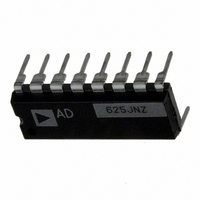
AD625JNZ
Description
IC AMP INST 25MHZ LN 16DIP
Manufacturer
Analog Devices Inc
Type
Low Noiser
Specifications of AD625JNZ
Amplifier Type
Instrumentation
Number Of Circuits
1
Slew Rate
5 V/µs
Gain Bandwidth Product
25MHz
-3db Bandwidth
650kHz
Current - Input Bias
30nA
Voltage - Input Offset
50µV
Current - Supply
3.5mA
Voltage - Supply, Single/dual (±)
±6 V ~ 18 V
Operating Temperature
0°C ~ 70°C
Mounting Type
Through Hole
Package / Case
16-DIP (0.300", 7.62mm)
Bandwidth
650 kHz
Common Mode Rejection Ratio
75
Current, Input Bias
±30 nA
Current, Input Offset
±2 nA
Current, Output
5 mA
Current, Supply
3.5 mA
Number Of Amplifiers
Five
Package Type
PDIP-16
Power Dissipation
450 mW
Resistance, Input
1 Gigaohms
Temperature, Operating, Range
0 to +70 °C
Voltage, Input Offset
50 μV
Voltage, Noise
4 nV/sqrt Hz
Voltage, Output Swing
±10 V
Voltage, Supply
±6 to ±18 V
No. Of Amplifiers
5
Input Offset Voltage
200µV
Gain Db Min
1dB
Amplifier Output
Single Ended
Cmrr
115dB
Supply Voltage Range
± 6V To ± 18V
Rohs Compliant
Yes
Lead Free Status / RoHS Status
Lead free / RoHS Compliant
Output Type
-
Current - Output / Channel
-
Lead Free Status / Rohs Status
RoHS Compliant part
Electrostatic Device
Available stocks
Company
Part Number
Manufacturer
Quantity
Price


AD625
GROUND RETURNS FOR BIAS CURRENTS
Input bias currents are those currents necessary to bias the input
transistors of a dc amplifier. There must be a direct return path
for these currents, otherwise they will charge external capaci-
tances, causing the output to drift uncontrollably or saturate.
Therefore, when amplifying “floating” input sources such as
transformers, or ac-coupled sources, there must be a dc path
from each input to ground as shown in Figure 35.
AUTOZERO CIRCUITS
In many applications it is necessary to maintain high accuracy.
At room temperature, offset effects can be nulled by the use of
offset trimpots. Over the operating temperature range, however,
offset nulling becomes a problem. For these applications the
autozero circuit of Figure 36 provides a hardware solution.
OTHER CONSIDERATIONS
One of the more overlooked problems in designing ultralow-
drift dc amplifiers is thermocouple induced offset. In a circuit
comprised of two dissimilar conductors (i.e., copper, kovar), a
current flows when the two junctions are at different tempera-
tures. When this circuit is broken, a voltage known as the
“Seebeck” or thermocouple emf can be measured. Standard IC
lead material (kovar) and copper form a thermocouple with a
100k
R
R
R
R
R
R
R
R
R
100k
G
G
G
F
F
F
F
F
F
AD625
AD625
AD625
+V
–V
+V
–V
+V
–V
S
S
S
S
S
S
REFERENCE
REFERENCE
REFERENCE
SENSE
SENSE
SENSE
LOAD
LOAD
LOAD
V
TO POWER
V
TO POWER
V
TO POWER
GROUND
GROUND
GROUND
OUT
SUPPLY
OUT
SUPPLY
OUT
SUPPLY
high thermoelectric potential (about 35 µV°C). This means that
care must be taken to insure that all connections (especially
those in the input circuit of the AD625) remain isothermal. This
includes the input leads (1, 16) and the gain sense lines (2, 15).
These pins were chosen for symmetry, helping to desensitize the
input circuit to thermal gradients. In addition, the user should
also avoid air currents over the circuitry since slowly fluctuating
thermocouple voltages will appear as “flicker” noise. In SPGA
applications relay contacts and CMOS mux leads are both
potential sources of additional thermocouple errors.
The base emitter junction of an input transistor can rectify out
of band signals (i.e., RF interference). When amplifying small
signals, these rectified voltages act as small dc offset errors. The
AD625 allows direct access to the input transistors’ bases and
emitters enabling the user to apply some first order filtering to
these unwanted signals. In Figure 37, the RC time constant
should be chosen for desired attenuation of the interfering signals.
In the case of a resistive transducer, the capacitance alone work-
ing against the internal resistance of the transducer may suffice.
V
ZERO PULSE
+
–
IN
15
GND
V
V
DD
SS
16
14
13
200 s
R
F
GND V
+GAIN SENSE
AD7502
+GAIN DRIVE
A1
FILTER
DD
CAP
+V
RTI NULL
RTI NULL
C
V
SS
REF
–V
+IN
NC
S
1
2
3
4
5
6
7
8
R
A2
AD625
10k
+IN
10k
A1
AD625
R
A3
A3
G
+V
–V
10k
S
A2
S
10k
–IN
A4
R
0.1 F LOW
16
15
14
13
12
11
10
LEAKAGE
9
SENSE
AD711
–GAIN SENSE
V
+V
–IN
–GAIN DRIVE
RTO
NULL
RTO
NULL
OUT
S
FILTER
CAP
AD7510DIKD
C
V
OUT
1k
12
11
R
F
9
10 V
OUT
Related parts for AD625JNZ
Image
Part Number
Description
Manufacturer
Datasheet
Request
R

Part Number:
Description:
±1.7g Dual-Axis IMEMS Accelerometer Evaluation Board
Manufacturer:
Analog Devices Inc
Datasheet:

Part Number:
Description:
Inertial Sensor Evaluation System
Manufacturer:
Analog Devices Inc
Datasheet:
Part Number:
Description:
Manufacturer:
Analog Devices Inc
Datasheet:
Part Number:
Description:
Manufacturer:
Analog Devices Inc
Datasheet:
Part Number:
Description:
Manufacturer:
Analog Devices Inc
Datasheet:
Part Number:
Description:
Manufacturer:
Analog Devices Inc
Datasheet:
Part Number:
Description:
Manufacturer:
Analog Devices Inc
Datasheet:
Part Number:
Description:
Manufacturer:
Analog Devices Inc
Datasheet:
Part Number:
Description:
Manufacturer:
Analog Devices Inc
Datasheet:
Part Number:
Description:
Manufacturer:
Analog Devices Inc
Datasheet:
Part Number:
Description:
Manufacturer:
Analog Devices Inc
Datasheet:
Part Number:
Description:
Manufacturer:
Analog Devices Inc
Datasheet:
Part Number:
Description:
Manufacturer:
Analog Devices Inc
Datasheet: