AD625JNZ Analog Devices Inc, AD625JNZ Datasheet - Page 2
AD625JNZ
Manufacturer Part Number
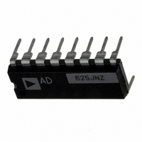
AD625JNZ
Description
IC AMP INST 25MHZ LN 16DIP
Manufacturer
Analog Devices Inc
Type
Low Noiser
Specifications of AD625JNZ
Amplifier Type
Instrumentation
Number Of Circuits
1
Slew Rate
5 V/µs
Gain Bandwidth Product
25MHz
-3db Bandwidth
650kHz
Current - Input Bias
30nA
Voltage - Input Offset
50µV
Current - Supply
3.5mA
Voltage - Supply, Single/dual (±)
±6 V ~ 18 V
Operating Temperature
0°C ~ 70°C
Mounting Type
Through Hole
Package / Case
16-DIP (0.300", 7.62mm)
Bandwidth
650 kHz
Common Mode Rejection Ratio
75
Current, Input Bias
±30 nA
Current, Input Offset
±2 nA
Current, Output
5 mA
Current, Supply
3.5 mA
Number Of Amplifiers
Five
Package Type
PDIP-16
Power Dissipation
450 mW
Resistance, Input
1 Gigaohms
Temperature, Operating, Range
0 to +70 °C
Voltage, Input Offset
50 μV
Voltage, Noise
4 nV/sqrt Hz
Voltage, Output Swing
±10 V
Voltage, Supply
±6 to ±18 V
No. Of Amplifiers
5
Input Offset Voltage
200µV
Gain Db Min
1dB
Amplifier Output
Single Ended
Cmrr
115dB
Supply Voltage Range
± 6V To ± 18V
Rohs Compliant
Yes
Lead Free Status / RoHS Status
Lead free / RoHS Compliant
Output Type
-
Current - Output / Channel
-
Lead Free Status / Rohs Status
RoHS Compliant part
Electrostatic Device
Available stocks
Company
Part Number
Manufacturer
Quantity
Price


AD625–SPECIFICATIONS
Model
GAIN
GAIN SENSE INPUT
VOLTAGE OFFSET (May be Nulled)
INPUT CURRENT
INPUT
OUTPUT RATING
DYNAMIC RESPONSE
Gain Equation
Gain Range
Gain Error
Nonlinearity, Gain = 1-256
Gain vs. Temp. Gain<1000
Gain Sense Current
Gain Sense Offset Current
Input Offset Voltage
Output Offset Voltage
Offset Referred to the
Input Bias Current
Input Offset Current
Input Impedance
Input Voltage Range
Common-Mode Rejection Ratio dc to
Small Signal –3 dB
Slew Rate
Settling Time to 0.01%, 20 V Step
vs. Temperature
vs. Temperature
vs. Temperature
vs. Temperature
Input vs. Supply
vs. Temperature
vs. Temperature
Differential Resistance
Differential Capacitance
Common-Mode Resistance
Common-Mode Capacitance
Differ. Input Linear (V
Common-Mode Linear (V
60 Hz with 1 kΩ Source Imbalance
G = 1 (R
G = 10
G = 100
G = 1000
G = 1 to 200
G = 500
G = 1000
G = 1
G = 10
G = 100
G = 1000
G = 1
G = 10
G = 100
G = 1000
1
F
= 20 kΩ)
Gain>256
DL
1
)
2
CM
)
Min Typ
1
70
85
95
100
70
90
100
110
12 V – G
AD625A/J/S
± .035
300
5
150
2
50
1
4
20
75
95
100
110
± 30
± 50
± 2
± 20
1
4
1
4
75
95
105
115
± 10 V
@ 5 mA
650
400
150
25
5.0
15
35
75
2 R
R
(
(typical @ V
G
2
F
×V
+ 1
Max
10,000
± 0.005
± 0.01
5
500
20
500
15
200
2/2
5
50/50
± 10
D
0.05
50
35
)
S
= 15 V, R
Min
1
75
90
105
110
75
90
105
110
12 V – G
AD625B/K
Typ
± 0.02
150
2
75
1
25
0.25
2
10
85
100
110
120
± 20
± 50
± 1
± 20
1
4
1
4
85
105
115
125
± 10 V
@ 5 mA
650
400
150
25
5.0
15
35
75
L
= 2 k
2 R
(
R
2
G
F
×V
+ 1
D
and T
Max
10,000
± 0.002
± 0.008
5
250
15
250
10
50
0.50/1
3
25/40
± 10
)
0.03
25
15
A
= + 25 C, unless otherwise noted)
Min
1
80
95
110
115
80
100
110
120
12 V – G
AD625C
Typ
± 0.01
50
2
50
2
10
0.1
1
10
90
105
120
140
± 10
± 50
± 1
± 20
1
4
1
4
90
115
125
140
± 10 V
@ 5 mA
650
400
150
25
5.0
15
35
75
2 R
(
R
2
G
F
×V
+ 1
D
Max
110,000
± 0.001
± 0.005
5
100
10
100
10
25
0.25
2
15
± 10
)
0.02
15
5
Unit
%
%
%
ppm/°C
nA
nA/°C
nA
nA/°C
µV
µV/°C
mV
µV/°C
dB
dB
dB
dB
nA
pA/°C
nA
pA/°C
GΩ
pF
GΩ
pF
V
dB
dB
dB
dB
kHz
kHz
kHz
kHz
V/µs
µs
µs
µs
Related parts for AD625JNZ
Image
Part Number
Description
Manufacturer
Datasheet
Request
R

Part Number:
Description:
±1.7g Dual-Axis IMEMS Accelerometer Evaluation Board
Manufacturer:
Analog Devices Inc
Datasheet:

Part Number:
Description:
Inertial Sensor Evaluation System
Manufacturer:
Analog Devices Inc
Datasheet:
Part Number:
Description:
Manufacturer:
Analog Devices Inc
Datasheet:
Part Number:
Description:
Manufacturer:
Analog Devices Inc
Datasheet:
Part Number:
Description:
Manufacturer:
Analog Devices Inc
Datasheet:
Part Number:
Description:
Manufacturer:
Analog Devices Inc
Datasheet:
Part Number:
Description:
Manufacturer:
Analog Devices Inc
Datasheet:
Part Number:
Description:
Manufacturer:
Analog Devices Inc
Datasheet:
Part Number:
Description:
Manufacturer:
Analog Devices Inc
Datasheet:
Part Number:
Description:
Manufacturer:
Analog Devices Inc
Datasheet:
Part Number:
Description:
Manufacturer:
Analog Devices Inc
Datasheet:
Part Number:
Description:
Manufacturer:
Analog Devices Inc
Datasheet:
Part Number:
Description:
Manufacturer:
Analog Devices Inc
Datasheet: