20-101-1221 Rabbit Semiconductor, 20-101-1221 Datasheet - Page 16
20-101-1221
Manufacturer Part Number
20-101-1221
Description
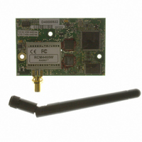
RCM4400W (JAPAN TELEC CERTIFIED)
Manufacturer
Rabbit Semiconductor
Series
RabbitCore®r
Datasheet
1.20-101-1202.pdf
(126 pages)
Specifications of 20-101-1221
Frequency
2.4GHz
Modulation Or Protocol
802.11 b
Power - Output
16dBm
Voltage - Supply
3.3V
Current - Receiving
450mA
Current - Transmitting
450mA
Data Interface
Connector, 2 x 25 Header
Memory Size
512K Flash, 1MB SRAM
Antenna Connector
SMA
Operating Temperature
-20°C ~ 85°C
Package / Case
Module
Lead Free Status / RoHS Status
Lead free / RoHS Compliant
Applications
-
Sensitivity
-
Data Rate - Maximum
-
Other names
316-1147


2.2 Hardware Connections
There are three steps to connecting the Prototyping Board for use with Dynamic C and the
sample programs:
1. Prepare the Prototyping Board for Development.
2. Attach the antenna to the RCM4400W module.
3. Attach the RCM4400W module to the Prototyping Board.
4. Connect the programming cable between the RCM4400W and the PC.
5. Connect the power supply to the Prototyping Board.
2.2.1 Step 1 — Prepare the Prototyping Board for Development
Snap in four of the plastic standoffs supplied in the bag of accessory parts from the Devel-
opment Kit in the holes at the corners as shown in Figure 2.
10
NOTE: Pay attention to use the hole that is pointed out towards the bottom left of the
Prototyping Board since the hole below it is used for a standoff when mounting the
RCM4400W on the Prototyping Board.
CAUTION: Provide ESD protection such as smocks and grounding straps on your
footwear.while assembling the RCM4400W module, installing it on another
board, and while making or removing any connections.
Remember to use ESD protection regardless of whether you are working with the
RCM4400W module on the Prototyping Board or in your own OEM application.
Figure 2. Insert Standoffs
RabbitCore RCM4400W
Related parts for 20-101-1221
Image
Part Number
Description
Manufacturer
Datasheet
Request
R

Part Number:
Description:
COMPUTER SGL-BRD BL2500 29.4MHZ
Manufacturer:
Rabbit Semiconductor
Datasheet:

Part Number:
Description:
COMPUTER SGL-BRD BL2500 29.4MHZ
Manufacturer:
Rabbit Semiconductor
Datasheet:

Part Number:
Description:
DISPLAY GRAPHIC 12KEY PROG OP670
Manufacturer:
Rabbit Semiconductor
Datasheet:
Part Number:
Description:
DISPLAY GRAPHIC 12KEY ETH OP6700
Manufacturer:
Rabbit Semiconductor
Datasheet:

Part Number:
Description:
COMPUTER SINGLE-BOARD BL2030
Manufacturer:
Rabbit Semiconductor
Part Number:
Description:
COMPUTER SGL-BOARD ETH BL2010
Manufacturer:
Rabbit Semiconductor

Part Number:
Description:
MODULE OP6810 W/O ETH/MEM EXPANS
Manufacturer:
Rabbit Semiconductor
Datasheet:
Part Number:
Description:
COMPUTER SINGLE-BOARD BL2020
Manufacturer:
Rabbit Semiconductor
Part Number:
Description:
COMPUTER BL2010 W/FRICTION LOCK
Manufacturer:
Rabbit Semiconductor
Part Number:
Description:
COMPUTER BL2020 W/FRICTION LOCK
Manufacturer:
Rabbit Semiconductor
Part Number:
Description:
COMPUTER SGL-BRD BL2500 44.2MHZ
Manufacturer:
Rabbit Semiconductor
Datasheet:
Part Number:
Description:
COMPUTER SGL-BOARD FULL BL2000
Manufacturer:
Rabbit Semiconductor

Part Number:
Description:
COMPUTER SINGLE-BOARD BL2110
Manufacturer:
Rabbit Semiconductor

Part Number:
Description:
COMPUTER SGL-BRD 29.4MHZ BL2610
Manufacturer:
Rabbit Semiconductor
Datasheet:
Part Number:
Description:
INTERFACE OP6800 512K FLASH&SRAM
Manufacturer:
Rabbit Semiconductor
Datasheet: