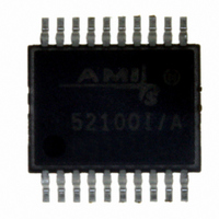
AMIS-52150-XTD ON Semiconductor, AMIS-52150-XTD Datasheet - Page 13

AMIS-52150-XTD
Manufacturer Part Number
AMIS-52150-XTD
Description
TXRX RF SUB 1GHZ CDR 20-SSOP
Manufacturer
ON Semiconductor
Datasheet
1.AMIS-52150-XTD.pdf
(25 pages)
Specifications of AMIS-52150-XTD
Frequency
300Mhz ~ 768MHz
Data Rate - Maximum
16kbps
Modulation Or Protocol
ASK, OOK
Applications
Wireless Modules
Power - Output
12dBm
Sensitivity
-117dBm
Voltage - Supply
2.3 V ~ 3.6 V
Current - Receiving
7.5mA
Current - Transmitting
25mA
Data Interface
PCB, Surface Mount
Antenna Connector
PCB, Surface Mount
Operating Temperature
0°C ~ 50°C
Package / Case
20-SSOP
Ic Interface Type
I2C
No. Of Tx Buffers
1
No. Of Rx Buffers
1
No. Of Filters
1
No. Of Interrupts
1
Supply Voltage Range
2.3V To 3.6V
Digital Ic Case Style
SSOP
No. Of Pins
20
Rohs Compliant
No
Operating Temperature (min)
0C
Operating Temperature Classification
Commercial
Modulation Type
ASK/OOK
Operating Supply Voltage (min)
2.3V
Operating Supply Voltage (typ)
3V
Operating Supply Voltage (max)
3.6V
Lead Free Status / RoHS Status
Lead free / RoHS Compliant
Memory Size
-
Lead Free Status / Rohs Status
Not Compliant
Other names
766-1020
Available stocks
Company
Part Number
Manufacturer
Quantity
Price
Company:
Part Number:
AMIS-52150-XTD
Manufacturer:
ON Semiconductor
Quantity:
135
AMIS-52150
Table 21: RF Input Electrical Characteristics
9.2 Transmitter
The RF transmitter is a non-linear open drain device. It requires a DC signal path to RFPWR, which is the output of the internal power
supply to the transmitter. The transmitter is switched On and Off with the serial transmit data stream. To achieve the desired output
waveform, a tuned external resonant circuit is required. This resonant circuit should be designed to achieve the desired output
frequency. This circuit includes a parallel LC tank (Lp and Cp) tuned to 402MHz (including internal capacitance), as well as a series LC
(Ls and Cs) to produce a 403MHz output. The transmitter output is also to be filtered in order to reduce the harmonics to acceptable
levels. It is further required that the transmitter output power level is programmed, that the transmit frequency is tuned and that the data
rate is selected, respectively (Table 22).
Table 23 lists some characteristic parameters for the transmitter, while a typical transmitter output waveform is shown in Fig. 8.
Table 22: Transmitter Control Registers
Specification
TX/RX Definition Control Registers
Register (HEX)
Input capacitance
Input resistance
Frequency
Sensitivity
Max. input
0x02
0x04
0x0c
0x1e
0x0f
IP3
IP2
Name
TX power
TX XTAL trim
TX enable
Data filter
TX/RX invert
Settings
Trim 0x00
Trim 0xff
4,5,6
Bits
Conditions
Min. tune
Max. tune
1 Kbps
All
All
4
5
States
000
001
010
011
100
101
110
111
0
1
0
1
Rev. 7 | Page 13 of 25 | www.onsemi.com
Typ.
2
3
6
-117
403.5
+8
+66
Figure 7: Received Waveform
Comments
Transmitter is off
Transmitter is on
1.1kHz
2.3kHz
5.2kHz
10.4kHz
1.18kHz
2.57kHz
7.0kHz
20.45kHz
Normal levels
Inverted
Max.
-10
Units
pFarads
pFarads
dBm
MHz
dBm
dBm
dBm
KΩ
Comments
w/CDR
Target frequency


