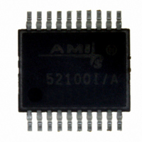
AMIS-52150-XTD ON Semiconductor, AMIS-52150-XTD Datasheet - Page 8

AMIS-52150-XTD
Manufacturer Part Number
AMIS-52150-XTD
Description
TXRX RF SUB 1GHZ CDR 20-SSOP
Manufacturer
ON Semiconductor
Datasheet
1.AMIS-52150-XTD.pdf
(25 pages)
Specifications of AMIS-52150-XTD
Frequency
300Mhz ~ 768MHz
Data Rate - Maximum
16kbps
Modulation Or Protocol
ASK, OOK
Applications
Wireless Modules
Power - Output
12dBm
Sensitivity
-117dBm
Voltage - Supply
2.3 V ~ 3.6 V
Current - Receiving
7.5mA
Current - Transmitting
25mA
Data Interface
PCB, Surface Mount
Antenna Connector
PCB, Surface Mount
Operating Temperature
0°C ~ 50°C
Package / Case
20-SSOP
Ic Interface Type
I2C
No. Of Tx Buffers
1
No. Of Rx Buffers
1
No. Of Filters
1
No. Of Interrupts
1
Supply Voltage Range
2.3V To 3.6V
Digital Ic Case Style
SSOP
No. Of Pins
20
Rohs Compliant
No
Operating Temperature (min)
0C
Operating Temperature Classification
Commercial
Modulation Type
ASK/OOK
Operating Supply Voltage (min)
2.3V
Operating Supply Voltage (typ)
3V
Operating Supply Voltage (max)
3.6V
Lead Free Status / RoHS Status
Lead free / RoHS Compliant
Memory Size
-
Lead Free Status / Rohs Status
Not Compliant
Other names
766-1020
Available stocks
Company
Part Number
Manufacturer
Quantity
Price
Company:
Part Number:
AMIS-52150-XTD
Manufacturer:
ON Semiconductor
Quantity:
135
AMIS-52150
8.3 LPFILT, Loop Filter Pin
The LPFILT pin connects the AMIS-52150 internal phase lock loop (PLL) frequency synthesizer to an external loop filter (Fig. 5). An
external loop filter allows the system designer to optimize the operation of the AMIS-52150 in order to meet the requirements for a
specific end application. For further details, refer to the application note titled “Extending to Frequencies Outside of the 403MHz
Target”.
8.4 RSSI/BG, Analog Output Pin
The RSSI/BG pin is used to output either the signal from the RSSI circuits, or to output the voltage from the bandgap voltage reference
or a bypass capacitor node, respectively. The RSSI output is a true analog representation of the received signal level. The pin can also
be programmed to output the voltage of the bandgap voltage reference. When using the AMIS-52150 in the clock and data recovery
mode, a capacitor needs to be connected from the RSSI/BG pin to ground. A typical value for this capacitor is 2.2nF. Additional
information on the CDR function can be found later in this document. Table 12 presents the registers that control the function of the
RSSI/BG pin.
Table 12: RSSVBG Pin Control Registers
*Note that device needs to be in RX, TX or crystal-on mode for bandgap voltage to be present on pin.
8.5 CREF, Current Reference Bias Pin
A resistor must be connected to the CREF pin to provide a current bias to the internal bandgap voltage reference circuit. It is critical
that this resistor value is 33.2KΩ (with one percent or better tolerance) to achieve proper operation of the bandgap voltage reference.
RSSI Pin Definition Control Registers
Register
(HEX)
0x0e
0x1e
Name
Bandgap on RSSI
RSSI Ext Amp
Bits
3
4
States
0
1
0
1
Rev. 7 | Page 8 of 25 | www.onsemi.com
Comments
Normal operation
BG output on RSSI*
Tri-stated
RSSI signal
Figure 5: Typical Loop Filter


