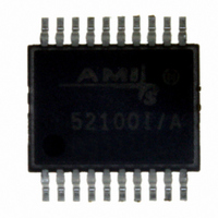
AMIS-52150-XTD ON Semiconductor, AMIS-52150-XTD Datasheet - Page 17

AMIS-52150-XTD
Manufacturer Part Number
AMIS-52150-XTD
Description
TXRX RF SUB 1GHZ CDR 20-SSOP
Manufacturer
ON Semiconductor
Datasheet
1.AMIS-52150-XTD.pdf
(25 pages)
Specifications of AMIS-52150-XTD
Frequency
300Mhz ~ 768MHz
Data Rate - Maximum
16kbps
Modulation Or Protocol
ASK, OOK
Applications
Wireless Modules
Power - Output
12dBm
Sensitivity
-117dBm
Voltage - Supply
2.3 V ~ 3.6 V
Current - Receiving
7.5mA
Current - Transmitting
25mA
Data Interface
PCB, Surface Mount
Antenna Connector
PCB, Surface Mount
Operating Temperature
0°C ~ 50°C
Package / Case
20-SSOP
Ic Interface Type
I2C
No. Of Tx Buffers
1
No. Of Rx Buffers
1
No. Of Filters
1
No. Of Interrupts
1
Supply Voltage Range
2.3V To 3.6V
Digital Ic Case Style
SSOP
No. Of Pins
20
Rohs Compliant
No
Operating Temperature (min)
0C
Operating Temperature Classification
Commercial
Modulation Type
ASK/OOK
Operating Supply Voltage (min)
2.3V
Operating Supply Voltage (typ)
3V
Operating Supply Voltage (max)
3.6V
Lead Free Status / RoHS Status
Lead free / RoHS Compliant
Memory Size
-
Lead Free Status / Rohs Status
Not Compliant
Other names
766-1020
Available stocks
Company
Part Number
Manufacturer
Quantity
Price
Company:
Part Number:
AMIS-52150-XTD
Manufacturer:
ON Semiconductor
Quantity:
135
AMIS-52150
A “kicker” circuit stimulates the crystal oscillator circuit with oscillations close to the final frequency. This significantly reduces the time it
takes for the oscillator to reach and lock to the final frequency. The Quick Start function is necessary for operation in Sniff Mode
Table 25 lists the Quick Start control registers. For further details, refer to the application note titled “Quick Start Crystal Oscillator
Circuit Operation and Set-up”.
Table 25: Quick Start Control Registers
9.5 Data Detection
The RSSI circuit creates an analog voltage waveform (18mV/dB) that follows the signal strength of the RF signal. The data slice circuit
then samples that waveform to create the digitized data. The slice circuit in the AMIS-52150 can be programmed to operate in one of
three modes; DAC mode, Average mode or Peak mode. The DAC mode compares a fixed slice threshold value to the level in the slice
output. The digital data state is determined by the level of the slice output being above or below that fixed threshold. For further details,
refer to the application note titled “Setting Up the AMIS-52150 Data Slicing Modes”. Figure 12 shows a typical waveform for the DAC
mode, while Table 26 shows the control registers for the auto slice modes.
In the Average mode, the threshold value is generated automatically. This threshold value is then compared to the output of the slice
circuit to re-create the digital data. The slice circuit along with an external capacitor are used to generate a charging time constant
which is equal to charging to 95 percent of a bit level in two bit time periods. The data protocol should add a header to the data to allow
the slice circuit to determine the average level. For further details, refer to the application note titled “Setting Up the AMIS-52150 Data
Slicing Modes”. Figure 13 shows a typical waveform for the Average mode. Table 26 shows the control registers for the auto slice
modes.
Quick Start Control Registers
Register (HEX)
0x03
0x0e
Name
Kicker Trim
Kick Config1
Kick Config2
Bits
All
4
5
States
Rev. 7 | Page 17 of 25 | www.onsemi.com
0
1
0
1
Figure 12: DAC Slice Mode Waveform
Comments
Trim the internal RC OSC to form a kick-start to the XTAL oscillator
Common mode clamp disabled (startup)
Common mode clamp enabled (normal)
Normal operation
Continuous kick On
TM
.


