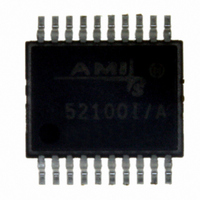
AMIS-52150-XTD ON Semiconductor, AMIS-52150-XTD Datasheet - Page 6

AMIS-52150-XTD
Manufacturer Part Number
AMIS-52150-XTD
Description
TXRX RF SUB 1GHZ CDR 20-SSOP
Manufacturer
ON Semiconductor
Datasheet
1.AMIS-52150-XTD.pdf
(25 pages)
Specifications of AMIS-52150-XTD
Frequency
300Mhz ~ 768MHz
Data Rate - Maximum
16kbps
Modulation Or Protocol
ASK, OOK
Applications
Wireless Modules
Power - Output
12dBm
Sensitivity
-117dBm
Voltage - Supply
2.3 V ~ 3.6 V
Current - Receiving
7.5mA
Current - Transmitting
25mA
Data Interface
PCB, Surface Mount
Antenna Connector
PCB, Surface Mount
Operating Temperature
0°C ~ 50°C
Package / Case
20-SSOP
Ic Interface Type
I2C
No. Of Tx Buffers
1
No. Of Rx Buffers
1
No. Of Filters
1
No. Of Interrupts
1
Supply Voltage Range
2.3V To 3.6V
Digital Ic Case Style
SSOP
No. Of Pins
20
Rohs Compliant
No
Operating Temperature (min)
0C
Operating Temperature Classification
Commercial
Modulation Type
ASK/OOK
Operating Supply Voltage (min)
2.3V
Operating Supply Voltage (typ)
3V
Operating Supply Voltage (max)
3.6V
Lead Free Status / RoHS Status
Lead free / RoHS Compliant
Memory Size
-
Lead Free Status / Rohs Status
Not Compliant
Other names
766-1020
Available stocks
Company
Part Number
Manufacturer
Quantity
Price
Company:
Part Number:
AMIS-52150-XTD
Manufacturer:
ON Semiconductor
Quantity:
135
AMIS-52150
Table 9: Package Dimensions ; 209mil SSOP
8.0 Pin Descriptions
8.1 RX1, RX2, RF Input Pins
RX1 and RX2 are the RF antenna inputs to the AMIS-52150. The internal circuit designs are identical between these inputs. For the
AMIS-52150 receiver inputs, RX1 and RX2, external components are required in order to match the low noise amplifier (LNA) to
external devices such as antennas. The external components must provide a DC voltage path to the RF ground. Figure 3 suggests an
external circuit for the receiver inputs at 403MHz. Each circuit’s input impedance can be trimmed internally to compensate for
manufacturing and external component tolerances. The circuits employ an LNA, internal filters, a low frequency, intermediate frequency
(IF), and a received signal strength indication (RSSI) circuit to recover the ASK/OOK modulated data. The signals in the two input
channels are “summed” before the data recovery circuit.
The functions of the receive circuits are controlled by writing to the registers shown in Table 10.
Table 10: Receiver Control Register Description
Dm
RX1 or RX2 Receiver Register Control
Register (HEX)
A1
A2
E1
A
D
E
b
e
0x00
0x01
0x0c
0.026 BSC
0.068
0.002
0.065
0.009
0.271
0.291
0.197
Min.
Name
ANT1 Trim
ANT2 Trim
ANT1 Enable
ANT2 Enable
Inches
0.078
0.073
0.015
0.295
0.323
0.221
Max.
.20
0.65 BSC
Bits
All
All
0
1
1.65`
Min.
1.73
0.05
0.22
6.90
7.40
5.00
Figure 3: Typical Input Impedance Match to 50Ω (402MHz)
Millimeters
States
Rev. 7 | Page 6 of 25 | www.onsemi.com
0
1
0
1
0.820
0.560
Max.
2.00
1.85
0.38
Comments
Inverse relationship register value to internal capacitance
Inverse relationship register value to internal capacitance
Antenna port is Off
Antenna port is On
Antenna port is Off
Antenna port is On
7.5


