AMIS-52150-XTD ON Semiconductor, AMIS-52150-XTD Datasheet - Page 19

AMIS-52150-XTD
Manufacturer Part Number
AMIS-52150-XTD
Description
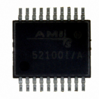
TXRX RF SUB 1GHZ CDR 20-SSOP
Manufacturer
ON Semiconductor
Datasheet
1.AMIS-52150-XTD.pdf
(25 pages)
Specifications of AMIS-52150-XTD
Frequency
300Mhz ~ 768MHz
Data Rate - Maximum
16kbps
Modulation Or Protocol
ASK, OOK
Applications
Wireless Modules
Power - Output
12dBm
Sensitivity
-117dBm
Voltage - Supply
2.3 V ~ 3.6 V
Current - Receiving
7.5mA
Current - Transmitting
25mA
Data Interface
PCB, Surface Mount
Antenna Connector
PCB, Surface Mount
Operating Temperature
0°C ~ 50°C
Package / Case
20-SSOP
Ic Interface Type
I2C
No. Of Tx Buffers
1
No. Of Rx Buffers
1
No. Of Filters
1
No. Of Interrupts
1
Supply Voltage Range
2.3V To 3.6V
Digital Ic Case Style
SSOP
No. Of Pins
20
Rohs Compliant
No
Operating Temperature (min)
0C
Operating Temperature Classification
Commercial
Modulation Type
ASK/OOK
Operating Supply Voltage (min)
2.3V
Operating Supply Voltage (typ)
3V
Operating Supply Voltage (max)
3.6V
Lead Free Status / RoHS Status
Lead free / RoHS Compliant
Memory Size
-
Lead Free Status / Rohs Status
Not Compliant
Other names
766-1020
Available stocks
Company
Part Number
Manufacturer
Quantity
Price
Company:
Part Number:
AMIS-52150-XTD
Manufacturer:
ON Semiconductor
Quantity:
135
AMIS-52150
Table 26: Auto Slice Control Registers
9.6 Data and Clock Recovery
Data recovered in a noisy environment or from a weak RF signal is usually jittery. The AMIS-52150 can remove much of that data jitter
by recovering a synchronous clock signal from the incoming data. The device can be set to achieve auto slice data detection. The clock
and data recovery circuits can be programmed to generate a data clock for synchronously clocking the data output from the transceiver,
removing much of the jitter in this process. The AMIS-52150 has an internal PLL that must be programmed to the frequency of the data
by setting the values in the FWORD register and setting the coefficients of the filter. If these values are close to the data rate, the
device will recover the data clock from the incoming detected data. The CDR circuit can also be set to a given tolerance with respect to
the frequency difference between the target data rate and the actual data rate, in order to improve the performance of the CDR
function. The CDR circuit can also be configured to reset after a programmed number of data time periods if no data is received. This
“stop and check” function allows the CDR circuit to re-acquire the clock data when new data is received, maintaining better clock to
data synchronization.
Table 27 lists the registers associated with the data and clock recovery function. For further details, refer to the application note titled
“AMIS-52150 Clock and Data Recovery Circuit Operation and Set-Up”.
Auto Slice Control Registers
Register (HEX)
0x0a
0x0f
Name
DATA SLICE
THRESHOLD
HYSTERESIS
AUTOSLICE
Bits
0,1
2,3
All
States
Rev. 7 | Page 19 of 25 | www.onsemi.com
00
01
10
11
00
01
10
11
Comments
Set a fixed reference level for the slice output to be
compared to in the DAC mode
0mV hysteresis used in the threshold circuit
20mV hysteresis used in the threshold circuit
50mV hysteresis used in the threshold circuit
100mV hysteresis used in the threshold circuit
DAC mode used for data detection (DEFAULT)
Average mode used for data detection
Peak mode used for data detection
DAC mode used for data detection


