GS-BT2416C2.AT1 STMicroelectronics, GS-BT2416C2.AT1 Datasheet
GS-BT2416C2.AT1
Specifications of GS-BT2416C2.AT1


Related parts for GS-BT2416C2.AT1


GS-BT2416C2.AT1 Summary of contents
Page 1
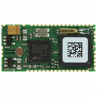
... SMA aerial or a low cost antenna trace designed on PCB. For more details pleas refer to GS-BT2416C2DBAT1 Application Note. The GS-BT2416C2.AT1 is the SPP with AT command module of the GS-BT2416C2.xx series. GS-BT2416C2.AT1 is BQB qualified. Conformance testing through Bluetooth qualification program enables a fast time to market after system integration by ensuring a high degree of compliance and interoperability ...
Page 2
... Usage scenarios . . . . . . . . . . . . . . . . . . . . . . . . . . . . . . . . . . . . . . . . . . . . 7 5 Application information . . . . . . . . . . . . . . . . . . . . . . . . . . . . . . . . . . . . . . 8 5.1 Antenna reference . . . . . . . . . . . . . . . . . . . . . . . . . . . . . . . . . . . . . . . . . . . 9 6 Block diagram . . . . . . . . . . . . . . . . . . . . . . . . . . . . . . . . . . . . . . . . . . . . . 10 7 Pin settings . . . . . . . . . . . . . . . . . . . . . . . . . . . . . . . . . . . . . . . . . . . . . . . 11 7.1 Pin connections . . . . . . . . . . . . . . . . . . . . . . . . . . . . . . . . . . . . . . . . . . . . 11 7.2 Pin descriptions . . . . . . . . . . . . . . . . . . . . . . . . . . . . . . . . . . . . . . . . . . . . 11 8 Mechanical dimensions . . . . . . . . . . . . . . . . . . . . . . . . . . . . . . . . . . . . . 14 Appendix A AT command . . . . . . . . . . . . . . . . . . . . . . . . . . . . . . . . . . . . . . . . . . . 15 A.1 Introduction . . . . . . . . . . . . . . . . . . . . . . . . . . . . . . . . . . . . . . . . . . . . . . . . 15 8.1 Description . . . . . . . . . . . . . . . . . . . . . . . . . . . . . . . . . . . . . . . . . . . . . . . . 15 A.2 Modes of operation . . . . . . . . . . . . . . . . . . . . . . . . . . . . . . . . . . . . . . . . . . 15 A.3 Interfaces A.4 Bluetooth features . . . . . . . . . . . . . . . . . . . . . . . . . . . . . . . . . . . . . . . . . . . 17 A.5 AT command reference . . . . . . . . . . . . . . . . . . . . . . . . . . . . . . . . . . . . . . . 18 2/32 GS-BT2416C2.AT1 ...
Page 3
... GS-BT2416C2.AT1 A A BTCMODE . . . . . . . . . . . . . . . . . . . . . . . . . . . . . . . . . . . . . . . . . . . . 19 A.8 AT+BTDMODE . . . . . . . . . . . . . . . . . . . . . . . . . . . . . . . . . . . . . . . . . . . . . 19 A.9 AT+BTPMODE . . . . . . . . . . . . . . . . . . . . . . . . . . . . . . . . . . . . . . . . . . . . . 19 A.10 AT+BTSECMODE . . . . . . . . . . . . . . . . . . . . . . . . . . . . . . . . . . . . . . . . . . . 20 A.11 AT+BTENCMODE . . . . . . . . . . . . . . . . . . . . . . . . . . . . . . . . . . . . . . . . . . . 20 A.12 AT+BTPINCODE . . . . . . . . . . . . . . . . . . . . . . . . . . . . . . . . . . . . . . . . . . . . 20 A.13 AT+BTERASELK A.14 AT+BTNAME . . . . . . . . . . . . . . . . . . . . . . . . . . . . . . . . . . . . . . . . . . . . . . . 21 A.15 AT+BTCLASS . . . . . . . . . . . . . . . . . . . . . . . . . . . . . . . . . . . . . . . . . . . . . . 21 A.16 AT+BTSETTINGS . . . . . . . . . . . . . . . . . . . . . . . . . . . . . . . . . . . . . . . . . . . 21 A.17 AT+BTINQ . . . . . . . . . . . . . . . . . . . . . . . . . . . . . . . . . . . . . . . . . . . . . . . . . 22 A.18 AT+BTRPORTS A.19 AT+BTREGPORT . . . . . . . . . . . . . . . . . . . . . . . . . . . . . . . . . . . . . . . . . . . 22 A.20 AT+BTMACROSTART . . . . . . . . . . . . . . . . . . . . . . . . . . . . . . . . . . . . . . . . 23 A.21 AT+BTMACROSTOP A.22 AT+BTMACROCLEAR . . . . . . . . . . . . . . . . . . . . . . . . . . . . . . . . . . . . . . . 23 A.23 AT+BTCONNECT . . . . . . . . . . . . . . . . . . . . . . . . . . . . . . . . . . . . . . . . . . . 24 A.24 AT+BTDISCONNECT . . . . . . . . . . . . . . . . . . . . . . . . . . . . . . . . . . . . . . . . 24 A.25 AT+ECHO . . . . . . . . . . . . . . . . . . . . . . . . . . . . . . . . . . . . . . . . . . . . . . . . . 25 A.26 AT+UARTSETUP . . . . . . . . . . . . . . . . . . . . . . . . . . . . . . . . . . . . . . . . . . . 25 A ...
Page 4
... Soldering temperature sold 1.2 Operating ranges Table 2. Operating ranges Symbol V Module supply voltage DD Operating ambient T stg temperature 4/32 Parameter Parameter Conditions - 20°C < T < 70 °C GS-BT2416C2.AT1 Values Unit Min Max 4 V Vss -0.5 Vdd+0 -40 +85 °C 240 Values Unit Min Typ Max 3 ...
Page 5
... GS-BT2416C2.AT1 2 Electrical characteristics 2.1 DC I/O specification Table 3. DC Input / Output specification Symbol V Low level input voltage il V High level input voltage ih V Schmitt trigger hysteresis hyst V Low level output voltage ol V High level output voltage oh 3 Bluetooth section Table 4. Bluetooth section ...
Page 6
... Parameter Conditions 2.402 GHz 2.441 GHz 2.480 GHz lM- lM-Nl ≥ 3 @BER 0.1% Parameter Conditions DH1 data packet DH3 data packet DH5 data packet Drift rate GS-BT2416C2.AT1 Min Typ Max Unit 0 dBm 0 dBm 0 dBm - 36 dBm - 50 dBm - 74 dBm Min Typ ...
Page 7
... GS-BT2416C2.AT1 4 Integrate software The GS-BT2416C2.AT1 implements the following Bluetooth protocols and profiles: ● L2CAP ● RFCOMM ● SDP ● Generic Access Profile (GAP) ● Serial Port Profile (SPP) Operated through AT command interpreter. Figure 1. AT1 software implementation Bluetooth Protocols and Profiles HCI Bottom Layer Hardware Layer 4 ...
Page 8
... Keep the RF ground separate from the module supply voltage ground; the two grounds are already connected inside the module in one point, see below a possible implementation. Figure 2. Module foot print 8/32 RF gnd Module foot print Supply voltage GND GS-BT2416C2.AT1 ...
Page 9
... GS-BT2416C2.AT1 5.1 Antenna reference RF output pin must be connected to an antenna which could be: ● Antenna directly printed on the pcb ● Integrated antenna as, for example, Antenova 30-30-A5839-01 , Murata ANCV12G44SAA127, Pulse W3008 , Yageo CAN4311153002451K. ● External antenna connected by means a SMA connector Figure 3. Antenna on PCB ● ...
Page 10
... Block diagram 6 Block diagram Figure 7. Block diagram UART USB PCM SPI I²C GPIO 10/32 32kHz 32kHz XTAL XTAL STLC2416 STLC2150 Baseband Radio chip ARM7 proc GS-BT2416C2.AT1 RF antenna Filter balun ...
Page 11
... GS-BT2416C2.AT1 7 Pin settings 7.1 Pin connections Figure 8. Pin connection diagram 7.2 Pin descriptions Table 7. Pin descriptions Pin N° Power, ground and system signal CLOCK OUT 6 General purpose signals Name I/O Vss --- GND 1 Vdd --- Module supply voltage- Single 3.3V RESET I Reset pin (active low) ...
Page 12
... PCM Data In/Out (1) PCM_B PCM Data In//Out (1) USB data - If not used connect to VSS1 (1) USB data + If not used connect to VSS1 I UART2 data input If not used connect to VDD O UART2 data output I UART2 clear to send input If not used connect to VDD O UART2 ready to send output GS-BT2416C2.AT1 Description ...
Page 13
... GS-BT2416C2.AT1 Table 7. Pin descriptions (continued) Pin N° SPI interface signals 17 SPI_FRM 18 SPI_CLK 19 SPI_TXD 20 SPI_RXD Antenna signals 43 Vss 44 +ANTENNA 45 Vss 1. Not used with AT command Name I/O (1) Synchronous Serial Interface frame synch (1) Synchronous Serial Interface clock (1) Synchronous Serial Interface transmit data Synchronous Serial Interface receive data If not used connect ...
Page 14
... Mechanical dimensions 8 Mechanical dimensions Figure 9. Mechanical dimensions Figure 10. Land pattern and connection diagram 14/32 GS-BT2416C2.AT1 ...
Page 15
... GS-BT2416C2.AT1 Appendix A AT command SPP Embedded Bluetooth™ firmware for STLC2416 based modules version 1.2.1.8 A.1 Introduction AT command interpreter OBSTFW-101 has been developed by Sycom on its proprietary Bluetooth stack Following data are disclosed with Sycom permission and agreement. All these information are subject to usual ST reproduction and disclosure rules stated on the last page of the present document ...
Page 16
... GPIO1: configured as output. GPIO1 is high when an SPP Bluetooth link to a remote device is present. GPIO1 is low when no Bluetooth link is present. ● GPIO3: configured as input. If GPIO3 is set to high the module switches its mode of operation to DATA MODE. If GPIO3 is set to low, the module switches its mode of operation to COMMAND MODE. 16/32 GS-BT2416C2.AT1 ...
Page 17
... GS-BT2416C2.AT1 A.4 Bluetooth features .AT1 implements the following Bluetooth protocols and profiles: ● L2CAP ● RFCOMM ● SDP ● Generic Access Profile (GAP) ● Serial Port Profile (SPP) The embedded SPP can be used in two modes: ● SERVER MODE: This mode allows the module to be connected by other devices. In this configuration the local module does not initiate a Bluetooth SPP connection, but simply exposes an SPP service that can be connected by other devices ...
Page 18
... Some AT commands can generate events. Events are always reported as follows: \0x0D\0x0A+EVENT: parameter0, …\0x0D\0x0A Each event is always bounded by the characters 0x0D 0x0A and can have zero or more parameters. The command syntax is case insensitive. A.6 AT Test the UART communication channel to the Bluetooth module Syntax: AT Return value: OK 18/32 GS-BT2416C2.AT1 ...
Page 19
... GS-BT2416C2.AT1 A BTCMODE Indicate if the module can be contacted by other Bluetooth devices. This command does not register any SPP service. Syntax: AT+BTCMODE=<0,1> Parameters: 0: The module cannot be contacted by other Bluetooth devices (default) 1: The module can be contacted by other Bluetooth devices Return value: <OK, ERROR> ...
Page 20
... In order to be successful, the module’s pin code and the connection pin code specified during a connection set-up must be identical. See AT+BTCONNECT for more information. Syntax: AT+BTPINCODE=”Pincode” Parameters: Pincode 16-byte string representing the module’s pin code Return value: <OK, ERROR> 20/32 GS-BT2416C2.AT1 ...
Page 21
... GS-BT2416C2.AT1 A.13 AT+BTERASELK Erase all link-keys. When all link-keys are erased the module is unpaired from all previously paired devices. Syntax: AT+BTERASELK Return value: <OK, ERROR> A.14 AT+BTNAME Set the local Bluetooth name. This name is the string shown to all other Bluetooth devices. ...
Page 22
... Register a local SPP service that can be opened by other remote Bluetooth devices. Syntax: AT+BTREGPORT=”PortName” Parameters: PortName: A string representing the name of the local SPP port. This name appears to remote devices when browsing local services. This string can be long up to 128 characters. Return value: <OK, ERROR> 22/32 GS-BT2416C2.AT1 ...
Page 23
... GS-BT2416C2.AT1 A.20 AT+BTMACROSTART Set the device in a programmable way. Every AT command coming after, with own parameters, will not be executed but will be stored in the very insertion order. This command will be available only if the device is set to COMMAND MODE. To notice that starting a macro storing sequence will erase any previous present sequence. ...
Page 24
... Return value: <OK, ERROR> A.24 AT+BTDISCONNECT Disconnect the current existing SPP Bluetooth link. When the link has been closed, the command returns an OK message and GPIO1 is set to low. Note: See AT+BTCONNECT Syntax: AT+BTDISCONNECT Return value: <OK, ERROR> 24/32 AT+BTCONNECT=BdAddress,PortN, GS-BT2416C2.AT1 “PinCode”,NRetry, TimeRetry ...
Page 25
... GS-BT2416C2.AT1 A.25 AT+ECHO Enable or disable the output of events and functional messages by the module. Syntax: AT+ECHO=<ON,OFF> Parameters: ON: The ECHO mode is enabled and every message or events by the module will be outputted. (default) OFF: The ECHO mode is disabled and no output will be generated. Return value: <OK, ERROR> ...
Page 26
... AT command A.28 AT+VER Requests the ID, version number and revision date of the firmware. The command generates a +VER event. Syntax: AT+VER Return value: +VER, <OK, ERROR> 26/32 GS-BT2416C2.AT1 ...
Page 27
... GS-BT2416C2.AT1 Appendix B AT event reference B.1 +BTSETTINGS Outputs the current configuration parameters of the module. Syntax: +BTSETTINGS: BdAddress, DeviceClass, “DeviceName”, “PinCode”, ConnectableMode, DiscoverableMode, PairableMode, SecurityMode, EncryptionMode Parameters: BdAddress: Bluetooth address of the local module. This value is specified byte hexadecimal value: i.e. ...
Page 28
... StopBits: possible values are 1 (default), 2 Fc: flow control. Possible values are None (default), Hardware B.4 +VER Indicates the ID, version number and revision date of the firmware. Syntax: +VER: ID, Ver, RevDate Parameters: ID: Firmware ID indicating the model Ver: Version of the firmware RevDate: Firmware revision date in DDMMYY format. 28/32 GS-BT2416C2.AT1 ...
Page 29
... GS-BT2416C2.AT1 B.5 +READY Indicates the module is ready to accept AT commands. The +READY message is generated when the module is started and when the mode is switched from DATA MODE to COMMAND MODE. Syntax: +READY Appendix C Application examples The following section provides two application examples demonstrating how two .AT1 equipped modules can be configured in order to act as a CLIENT and as a SERVER and connect to each other using the SPP service ...
Page 30
... TimeRetry parameter is ignored. First, an inquiry is performed to discover nearby Bluetooth devices. Once all devices have been found a connection is made to the found device (SERVER). AT+BTINQ=10 +BTINQRES: 00800010AA02, ”SPP Server” OK AT+BTRPORTS=00800010AA02 +BTRPORT: “SPP Port” AT+BTCONNECT=00800010AA02, 1, “1234” 30/32 GS-BT2416C2.AT1 ...
Page 31
... GS-BT2416C2.AT1 9 Revision history Table 8. Document revision history Date 03-Sep-2007 Revision 1 First release Revision history Changes 31/32 ...
Page 32
... Australia - Belgium - Brazil - Canada - China - Czech Republic - Finland - France - Germany - Hong Kong - India - Israel - Italy - Japan - Malaysia - Malta - Morocco - Singapore - Spain - Sweden - Switzerland - United Kingdom - United States of America 32/32 Please Read Carefully: © 2007 STMicroelectronics - All rights reserved STMicroelectronics group of companies www.st.com GS-BT2416C2.AT1 ...