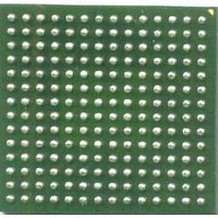
MCF53014CMJ240J Freescale Semiconductor, MCF53014CMJ240J Datasheet - Page 44

MCF53014CMJ240J
Manufacturer Part Number
MCF53014CMJ240J
Description
IC MCU 32BIT 128KB 256MAPBGA
Manufacturer
Freescale Semiconductor
Series
MCF5301xr
Datasheet
1.MCF53010CQT240.pdf
(62 pages)
Specifications of MCF53014CMJ240J
Core Processor
Coldfire V3
Core Size
32-Bit
Speed
240MHz
Connectivity
EBI/EMI, Ethernet, I²C, MMC, SPI, SSI, UART/USART, USB, USB OTG
Peripherals
DMA, PWM, WDT
Number Of I /o
83
Program Memory Size
16KB (16K x 8)
Program Memory Type
Cache
Ram Size
128K x 8
Voltage - Supply (vcc/vdd)
1.08 V ~ 3.6 V
Oscillator Type
Internal
Operating Temperature
-40°C ~ 85°C
Package / Case
256-LBGA
Processor Series
MCF5301x
Core
ColdFire V3
Data Bus Width
32 bit
Data Ram Size
16 bit
Interface Type
I2C, UART, DSPI
Maximum Clock Frequency
400 KHz, 20 MHz, 25 MHz
Number Of Timers
4
Operating Supply Voltage
- 0.5 V to + 2 V
Maximum Operating Temperature
+ 85 C
Mounting Style
SMD/SMT
3rd Party Development Tools
JLINK-CF-BDM26, EWCF
Development Tools By Supplier
M53015EVB, M53017KIT, M53017MOD
Minimum Operating Temperature
- 40 C
On-chip Adc
13 bit
On-chip Dac
16 bit
Lead Free Status / RoHS Status
Lead free / RoHS Compliant
Eeprom Size
-
Data Converters
-
Lead Free Status / Rohs Status
Details
Available stocks
Company
Part Number
Manufacturer
Quantity
Price
Company:
Part Number:
MCF53014CMJ240J
Manufacturer:
Freescale Semiconductor
Quantity:
10 000
1
2
3
Preliminary Electrical Characteristics
5.17.2
5.17.2.1
The reset sequence for this kind of SIM card is as follows (see
5.17.2.2
The sequence of reset for this kind of card is as follows (see
44
Num
SIM_VEN
SIM_CLK
50% duty cycle clock
With C = 50pF
With C = 50pF
SIM_RX
1
2
3
4
•
•
•
1.
2.
3.
4.
5.
After powerup, the clock signal is enabled on SIM_CLK (time T0)
After 200 clock cycles, RX must be high.
The card must send a response on RX acknowledging the reset between 400 and 40,000 clock cycles after T0.
After powerup, the clock signal is enabled on SIM_CLK (time T0)
After 200 clock cycles, RX must be high.
SIM_RST must remain low for at least 40,000 clock cycles after T0 (no response is to be received on RX during those
40,000 clock cycles)
SIM_RST is set high (time T1)
SIM_RST must remain high for at least 40,000 clock cycles after T1 and a response must be received on RX between
400 and 40,000 clock cycles after T1.
SIM Clock Frequency (SIM_CLK)
SIM_CLK Rise Time
SIM_CLK Fall Time
SIM Input Transition Time (RX, SIM_PD)
Reset Sequence
Cards with Internal Reset
Cards with Active-Low Reset
T0
1
Description
3
Table 29. SIM Timing Specification—High Drive Strength
2
2
Figure 31. Internal-Reset Card Reset Sequence
Preliminary—Subject to Change Without Notice
1
MCF5301x Data Sheet, Rev. 5
Response
Symbol
Figure
S
S
S
S
trans
Figure
freq
rise
fall
400 clock cycles <
32):
31):
0.01
Min
–
–
–
5 (Some new cards
1
2
may reach 10)
< 200 clock cycles
< 40,000 clock cycles
Max
20
20
25
Freescale Semiconductor
MHz
Unit
ns
ns
ns


