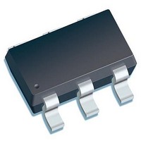
ILD 4035 E6327 Infineon Technologies, ILD 4035 E6327 Datasheet - Page 16

ILD 4035 E6327
Manufacturer Part Number
ILD 4035 E6327
Description
LED Drivers LED DRIVER
Manufacturer
Infineon Technologies
Datasheet
1.ILD_4035_E6327.pdf
(29 pages)
Specifications of ILD 4035 E6327
Low Level Output Current
350 mA
High Level Output Current
500 mA
Operating Supply Voltage
4.5 V to 42 V
Maximum Power Dissipation
1000 mW
Maximum Operating Temperature
+ 150 C
Mounting Style
SMD/SMT
Package / Case
SC-74-6
Minimum Operating Temperature
- 65 C
Lead Free Status / RoHS Status
Lead free / RoHS Compliant
Other names
ILD4035E6327XT
ILD4035
350 mA LED Driver
Basic Application Information
PWM Dimming
The EM/PWM terminal on the PCB is an input for the pulse width modulated (PWM) signal to control the dimming
of the LED string. The PWM signal's logic high level should be at least 2.6 V or higher. The period of this PWM
signal should be higher than 200 us. For the default demo board circuit, a dimming frequency less than 300 Hz is
recommended to maintain a maximum contrast ratio of at least 100:1. The maximum contrast ratio is shown on
Figure
7, and the minimum is based on the measured average LED current at 3dB below the linear reference. The
maximum contrast ratio depends largely on the rise time of the inductor current, and hence is dependent on input
voltage, inductor size, and LED string forward voltage.
Figure 7
ILD4035; PWM Dimming
Data Sheet
16
Revision 1.0, 2010-11-11


