OM11049,598 NXP Semiconductors, OM11049,598 Datasheet - Page 48
OM11049,598
Manufacturer Part Number
OM11049,598
Description
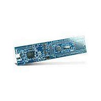
MCU, MPU & DSP Development Tools LPC1114 Demo Boards Cortex M0
Manufacturer
NXP Semiconductors
Datasheet
1.OM11049598.pdf
(66 pages)
Specifications of OM11049,598
Processor To Be Evaluated
LPC1114
Processor Series
LPC11xx
Interface Type
I2C, SPI
Maximum Operating Temperature
+ 85 C
Minimum Operating Temperature
- 40 C
Operating Supply Voltage
3.3 V
Tool Type
Demonstration Board
Core Architecture
ARM
Cpu Core
ARM Cortex M0
Data Bus Width
32 bit
Lead Free Status / RoHS Status
Lead free / RoHS Compliant


NXP Semiconductors
10. Dynamic characteristics
LPC1111_12_13_14
Product data sheet
10.1 Power-up ramp conditions
10.2 Flash memory
Table 11.
T
[1]
[2]
Table 12.
T
[1]
[2]
Symbol Parameter
t
t
V
Symbol
N
t
t
t
r
wait
ret
er
prog
amb
amb
Fig 24. Power-up ramp
I
endu
See
The wait time specifies the time the power supply must be at levels below 400 mV before ramping up.
Number of program/erase cycles.
Programming times are given for writing 256 bytes from RAM to the flash. Data must be written to the flash
in blocks of 256 bytes.
= −40 °C to +85 °C.
= −40 °C to +85 °C, unless otherwise specified.
Figure
Condition: 0 < V
rise time
wait time
input voltage
Power-up characteristics
Flash characteristics
Parameter
endurance
retention time
erase time
programming
time
24.
All information provided in this document is subject to legal disclaimers.
Rev. 4 — 10 February 2011
I
≤ 400 mV at start of power-up (t = t
400 mV
Conditions
at t = t
at t = t
V
DD
0
Conditions
powered
unpowered
sector or multiple
consecutive
sectors
1
1
: 0 < V
on pin V
I
≤ 400 mV
DD
t = t
1
32-bit ARM Cortex-M0 microcontroller
[1]
[2]
1
)
LPC1111/12/13/14
Min
10000
10
20
95
0.95
t
wait
[1][2]
t
r
[1]
002aag001
Min
0
12
0
Typ
100000
-
-
100
1
Typ
-
-
-
© NXP B.V. 2011. All rights reserved.
Max
500
-
400
Max
-
-
-
105
1.05
48 of 66
Unit
ms
μs
mV
Unit
cycles
years
years
ms
ms
Related parts for OM11049,598
Image
Part Number
Description
Manufacturer
Datasheet
Request
R

Part Number:
Description:
NXP Semiconductors designed the LPC2420/2460 microcontroller around a 16-bit/32-bitARM7TDMI-S CPU core with real-time debug interfaces that include both JTAG andembedded trace
Manufacturer:
NXP Semiconductors
Datasheet:

Part Number:
Description:
NXP Semiconductors designed the LPC2458 microcontroller around a 16-bit/32-bitARM7TDMI-S CPU core with real-time debug interfaces that include both JTAG andembedded trace
Manufacturer:
NXP Semiconductors
Datasheet:
Part Number:
Description:
NXP Semiconductors designed the LPC2468 microcontroller around a 16-bit/32-bitARM7TDMI-S CPU core with real-time debug interfaces that include both JTAG andembedded trace
Manufacturer:
NXP Semiconductors
Datasheet:
Part Number:
Description:
NXP Semiconductors designed the LPC2470 microcontroller, powered by theARM7TDMI-S core, to be a highly integrated microcontroller for a wide range ofapplications that require advanced communications and high quality graphic displays
Manufacturer:
NXP Semiconductors
Datasheet:
Part Number:
Description:
NXP Semiconductors designed the LPC2478 microcontroller, powered by theARM7TDMI-S core, to be a highly integrated microcontroller for a wide range ofapplications that require advanced communications and high quality graphic displays
Manufacturer:
NXP Semiconductors
Datasheet:
Part Number:
Description:
The Philips Semiconductors XA (eXtended Architecture) family of 16-bit single-chip microcontrollers is powerful enough to easily handle the requirements of high performance embedded applications, yet inexpensive enough to compete in the market for hi
Manufacturer:
NXP Semiconductors
Datasheet:
Part Number:
Description:
The XA-S3 device is a member of Philips Semiconductors? XA(eXtended Architecture) family of high performance 16-bitsingle-chip microcontrollers
Manufacturer:
NXP Semiconductors
Datasheet:

Part Number:
Description:
The NXP BlueStreak LH75401/LH75411 family consists of two low-cost 16/32-bit System-on-Chip (SoC) devices
Manufacturer:
NXP Semiconductors
Datasheet:
Part Number:
Description:
The NXP LPC3130/3131 combine an 180 MHz ARM926EJ-S CPU core, high-speed USB2
Manufacturer:
NXP Semiconductors
Datasheet:
Part Number:
Description:
The NXP LPC3141 combine a 270 MHz ARM926EJ-S CPU core, High-speed USB 2
Manufacturer:
NXP Semiconductors
Part Number:
Description:
The NXP LPC3143 combine a 270 MHz ARM926EJ-S CPU core, High-speed USB 2
Manufacturer:
NXP Semiconductors

Part Number:
Description:
The NXP LPC3152 combines an 180 MHz ARM926EJ-S CPU core, High-speed USB 2
Manufacturer:
NXP Semiconductors
Part Number:
Description:
The NXP LPC3154 combines an 180 MHz ARM926EJ-S CPU core, High-speed USB 2
Manufacturer:
NXP Semiconductors

Part Number:
Description:
Standard level N-channel enhancement mode Field-Effect Transistor (FET) in a plastic package using NXP High-Performance Automotive (HPA) TrenchMOS technology
Manufacturer:
NXP Semiconductors
Datasheet: