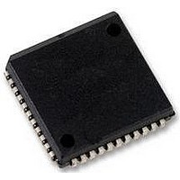
SC28L92A1A NXP Semiconductors, SC28L92A1A Datasheet - Page 45

SC28L92A1A
Manufacturer Part Number
SC28L92A1A
Description
UART, DUAL, 3.3V OR 5V, SMD, 28L92
Manufacturer
NXP Semiconductors
Datasheet
1.SC28L92A1B557.pdf
(73 pages)
Specifications of SC28L92A1A
No. Of Channels
2
Supply Voltage Range
2.97V To 3.63V, 4.5V To 5.5V
Operating Temperature Range
-40°C To +85°C
Digital Ic Case Style
PLCC
No. Of Pins
44
Svhc
No SVHC (18-Jun-2010)
Operating
RoHS Compliant
Data Rate
230.4Kilobaud
Uart Features
Programmable Channel Mode, Line Break Detection & Generation
Rohs Compliant
Yes
Available stocks
Company
Part Number
Manufacturer
Quantity
Price
Company:
Part Number:
SC28L92A1A
Manufacturer:
NXP
Quantity:
677
Company:
Part Number:
SC28L92A1A,512
Manufacturer:
NXP Semiconductors
Quantity:
10 000
Company:
Part Number:
SC28L92A1A,518
Manufacturer:
NXP Semiconductors
Quantity:
10 000
Company:
Part Number:
SC28L92A1A,529
Manufacturer:
NXP Semiconductors
Quantity:
10 000
Company:
Part Number:
SC28L92A1A529
Manufacturer:
NXP Semiconductors
Quantity:
135
NXP Semiconductors
SC28L92_7
Product data sheet
7.3.10 Input Port Change Register (IPCR)
7.3.11 Interrupt Status Register (ISR)
Table 55.
Table 56.
This register provides the status of all potential interrupt sources. The contents of this
register are masked by the Interrupt Mask Register (IMR). If a bit in the ISR is a logic 1
and the corresponding bit in the IMR is also a logic 1, the INTRN output will be asserted
(LOW). If the corresponding bit in the IMR is a zero, the state of the bit in the ISR has no
effect on the INTRN output. Note that the IMR does not mask the reading of the ISR. The
true status will be provided regardless of the contents of the IMR. The contents of this
register are initialized to 0x0 when the DUART is reset.
Table 57.
Table 58.
Bit
7 to 4
3 to 0
Bit
7
input port
delta IP3
change
7
7
Symbol
-
Symbol
-
-
IPCR - Input port change register (address 0x4) bit allocation
IPCR - Input port change register (address 0x4) bit description
ISR - Interrupt status register (address 0x5) bit allocation
ISR - Interrupt status register (address 0x5) bit description
delta IP2
break B
change
6
6
Description
Input port change status.
This bit is a logic 1 when a change of state has occurred at the IP0, IP1, IP2, or
IP3 inputs and that event has been selected to cause an interrupt by the
programming of ACR[3:0]. The bit is cleared when the CPU reads the IPCR.
Description
IP3, IP2, IP1 and IP0 change of state.
These bits are set when a change of state, as defined in
port”, occurs at the respective input pins. They are cleared when the IPCR is
read by the CPU. A read of the IPCR also clears ISR[7], the input change bit in
the interrupt status register. The setting of these bits can be programmed to
generate an interrupt to the CPU.
IP3, IP2, IP1 and IP0 state.
These bits provide the current state of the respective inputs. The information is
unlatched and reflects the state of the input pins at the time the IPCR is read.
0 = not active
1 = active
0 = no change
1 = change
0 = LOW
1 = HIGH
Rev. 07 — 19 December 2007
3.3 V/5.0 V Dual Universal Asynchronous Receiver/Transmitter
delta IP1
RxRDYB
5
5
delta IP0
TxRDYB
4
4
state of
counter
ready
IP3
3
3
break A
state of
change
IP2
2
2
Section 6.2.9 “Input
RxRDYA
state of
SC28L92
© NXP B.V. 2007. All rights reserved.
IP1
1
1
TxRDYA
state of
IP0
45 of 73
0
0


