EP3C10M164C8N Altera, EP3C10M164C8N Datasheet - Page 106
EP3C10M164C8N
Manufacturer Part Number
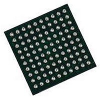
EP3C10M164C8N
Description
IC CYCLONE III FPGA 402MHZ BGA-164
Manufacturer
Altera
Series
Cyclone IIIr
Specifications of EP3C10M164C8N
No. Of Logic Blocks
645
Family Type
Cyclone III
No. Of I/o's
106
I/o Supply Voltage
3.3V
Operating Frequency Max
402MHz
Operating Temperature Range
0°C To +85°C
Family Name
Cyclone III
Number Of Logic Blocks/elements
10320
# I/os (max)
106
Frequency (max)
402MHz
Process Technology
65nm
Operating Supply Voltage (typ)
1.2V
Logic Cells
10320
Ram Bits
423936
Operating Supply Voltage (min)
1.15V
Operating Supply Voltage (max)
1.25V
Operating Temp Range
0C to 85C
Operating Temperature Classification
Commercial
Mounting
Surface Mount
Pin Count
164
Package Type
MBGA
Lead Free Status / RoHS Status
Lead free / RoHS Compliant
Lead Free Status / RoHS Status
Lead free / RoHS Compliant
Available stocks
Company
Part Number
Manufacturer
Quantity
Price


6–6
PCI-Clamp Diode
Cyclone III Device Handbook, Volume 1
f
f
f
The IOE registers in each I/O block share the same source for the preset or clear
features. You can program preset or clear for each individual IOE, but you cannot use
both features simultaneously. You can also program the registers to power-up high or
low after configuration is complete. If programmed to power-up low, an
asynchronous clear can control the registers. If programmed to power-up high, an
asynchronous preset can control the registers. This feature prevents the inadvertent
activation of the active-low input of another device upon power up. If one register in
an IOE uses a preset or clear signal, all registers in the IOE must use that same signal if
they require preset or clear. Additionally, a synchronous reset signal is available for
the IOE registers.
For more information about the input and output pin delay settings, refer to the
and Timing Optimization
The Cyclone III device family provides an optional PCI-clamp diode enabled input
and output for each I/O pin. Dual-purpose configuration pins support the diode in
user mode if the specific pins are not used as configuration pins for the selected
configuration scheme. For example, if you are using the active serial (AS)
configuration scheme, you cannot use the clamp diode on the ASDO and nCSO pins in
user mode. Dedicated configuration pins do not support the on-chip diode.
The PCI-clamp diode is available for the following I/O standards:
■
■
■
■
■
■
■
If the input I/O standard is 3.3-V LVTTL, 3.3-V LVCMOS, 3.0-V LVTTL, 3.0-V
LVCMOS, 2.5-V LVTTL/LVCMOS, PCI, or PCI-X, the PCI clamp diode is enabled by
default in the Quartus II software.
For more information, refer to the
Quartus II Handbook.
For more information about the Cyclone III device family PCI-clamp diode support,
refer to
Systems.
3.3-V LVTTL
3.3-V LVCMOS
3.0-V LVTTL
3.0-V LVCMOS
2.5-V LVTTL/LVCMOS
PCI
PCI-X
AN 447: Interfacing Cyclone III Devices with 3.3/3.0/2.5-V LVTTL/LVCMOS I/O
chapter in volume 2 of the Quartus II Handbook.
Assignment Editor
Chapter 6: I/O Features in the Cyclone III Device Family
chapter in volume 2 of the
© December 2009 Altera Corporation
I/O Element Features
Area
Related parts for EP3C10M164C8N
Image
Part Number
Description
Manufacturer
Datasheet
Request
R

Part Number:
Description:
CYCLONE II STARTER KIT EP2C20N
Manufacturer:
Altera
Datasheet:


Part Number:
Description:
CPLD, EP610 Family, ECMOS Process, 300 Gates, 16 Macro Cells, 16 Reg., 16 User I/Os, 5V Supply, 35 Speed Grade, 24DIP
Manufacturer:
Altera Corporation
Datasheet:
Part Number:
Description:
CPLD, EP610 Family, ECMOS Process, 300 Gates, 16 Macro Cells, 16 Reg., 16 User I/Os, 5V Supply, 15 Speed Grade, 24DIP
Manufacturer:
Altera Corporation
Datasheet:
Part Number:
Description:
Manufacturer:
Altera Corporation
Datasheet:
Part Number:
Description:
CPLD, EP610 Family, ECMOS Process, 300 Gates, 16 Macro Cells, 16 Reg., 16 User I/Os, 5V Supply, 30 Speed Grade, 24DIP
Manufacturer:
Altera Corporation
Datasheet:
Part Number:
Description:
High-performance, low-power erasable programmable logic devices with 8 macrocells, 10ns
Manufacturer:
Altera Corporation
Datasheet:
Part Number:
Description:
High-performance, low-power erasable programmable logic devices with 8 macrocells, 7ns
Manufacturer:
Altera Corporation
Datasheet:
Part Number:
Description:
Classic EPLD
Manufacturer:
Altera Corporation
Datasheet:
Part Number:
Description:
High-performance, low-power erasable programmable logic devices with 8 macrocells, 10ns
Manufacturer:
Altera Corporation
Datasheet:
Part Number:
Description:
Manufacturer:
Altera Corporation
Datasheet:
Part Number:
Description:
Manufacturer:
Altera Corporation
Datasheet:
Part Number:
Description:
Manufacturer:
Altera Corporation
Datasheet:
Part Number:
Description:
CPLD, EP610 Family, ECMOS Process, 300 Gates, 16 Macro Cells, 16 Reg., 16 User I/Os, 5V Supply, 25 Speed Grade, 24DIP
Manufacturer:
Altera Corporation
Datasheet: