IP-POSPHY4 Altera, IP-POSPHY4 Datasheet - Page 27
IP-POSPHY4
Manufacturer Part Number
IP-POSPHY4
Description
IP CORE - POS-PHY Level 4 SPI 4.2 Interface
Manufacturer
Altera
Type
MegaCorer
Datasheet
1.IP-POSPHY4.pdf
(144 pages)
Specifications of IP-POSPHY4
Software Application
IP CORE, Interface And Protocols, COMMUNICATION
Supported Families
Arria GX, Cyclone, HardCopy, Stratix
Core Architecture
FPGA
Core Sub-architecture
Arria, Cyclone, Stratix
Rohs Compliant
NA
Function
POS-PHY Level 4 Interface, Link-Layer/PHY Layer
License
Initial License
Lead Free Status / RoHS Status
na
Lead Free Status / RoHS Status
na


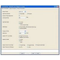
Chapter 3: Parameter Settings
Basic Parameters
December 2010 Altera Corporation
Atlantic FIFO Buffer Clock
Atlantic Interface Width
1
1
■
■
■
■
■
The Atlantic FIFO buffer clock sets the clock mode for the Atlantic FIFO buffers. Two
choices are available: Single or Multiple.
With a single Atlantic FIFO buffer clock, the Atlantic FIFO buffers are instantiated as
single clock domain buffers that do not include any clock crossing logic and therefore
consume fewer logic resources.
With a multiple Atlantic FIFO buffer clocks, the Atlantic FIFO buffers are instantiated
as multiple clock domain buffers. Each buffer has two independently operated clock
inputs, thus each Atlantic interface has a separate clock input. Multiple Atlantic FIFO
buffer clocks consume more logic resources.
The Atlantic interface width includes 32, 64, or 128 bits, and depends on the internal
data path width.
data path width.
For the individual buffers mode, all buffers have the same data path width.
Table 3–2. Atlantic Interface Data Width Limitations
The Status channel clock edge determines on which clock edge—positive (rising),
negative (falling), or programmable—the 2-bit status channel is transmitted (by the
receiver MegaCore function) in reference to the tsclk (for the transmitter) or rsclk
(for the receiver) pin. When you turn on Programmable Edge, an input pin,
(ctl_ts_statedge for the transmitter; ctl_rs_statedge for the receiver), controls the
status channel clocking edge statically at reset.
To ensure proper sampling of the status information, you should typically set this
parameter to be the opposite of the sampling clock edge on the adjacent device.
For the Status channel I/O standard, either LVTTL or LVDS, select LVDS to
implement the optional lower bandwidth LVDS status operation (refer to the OIF-
SPI4-02.1 specification).
2,048 bytes
4,096 bytes
8,192 bytes
16,384 bytes
32,768 bytes
Internal Data Path Width (Bits)
Table 3–2
128
64
32
shows the Atlantic data widths supported for each internal
Supported Atlantic Data Width (Bits)
POS-PHY Level 4 MegaCore Function User Guide
64 and 128
32 and 64
128
3–5
Related parts for IP-POSPHY4
Image
Part Number
Description
Manufacturer
Datasheet
Request
R

Part Number:
Description:
IP CORE Renewal Of IP-POSPHY4
Manufacturer:
Altera
Datasheet:

Part Number:
Description:
IP Thermal Transfer Printer With Peel/Present Option
Manufacturer:
BRADY

Part Number:
Description:
CYCLONE II STARTER KIT EP2C20N
Manufacturer:
Altera
Datasheet:


Part Number:
Description:
CPLD, EP610 Family, ECMOS Process, 300 Gates, 16 Macro Cells, 16 Reg., 16 User I/Os, 5V Supply, 35 Speed Grade, 24DIP
Manufacturer:
Altera Corporation
Datasheet:
Part Number:
Description:
CPLD, EP610 Family, ECMOS Process, 300 Gates, 16 Macro Cells, 16 Reg., 16 User I/Os, 5V Supply, 15 Speed Grade, 24DIP
Manufacturer:
Altera Corporation
Datasheet:
Part Number:
Description:
Manufacturer:
Altera Corporation
Datasheet:
Part Number:
Description:
CPLD, EP610 Family, ECMOS Process, 300 Gates, 16 Macro Cells, 16 Reg., 16 User I/Os, 5V Supply, 30 Speed Grade, 24DIP
Manufacturer:
Altera Corporation
Datasheet:
Part Number:
Description:
High-performance, low-power erasable programmable logic devices with 8 macrocells, 10ns
Manufacturer:
Altera Corporation
Datasheet:
Part Number:
Description:
High-performance, low-power erasable programmable logic devices with 8 macrocells, 7ns
Manufacturer:
Altera Corporation
Datasheet:
Part Number:
Description:
Classic EPLD
Manufacturer:
Altera Corporation
Datasheet:
Part Number:
Description:
High-performance, low-power erasable programmable logic devices with 8 macrocells, 10ns
Manufacturer:
Altera Corporation
Datasheet:
Part Number:
Description:
Manufacturer:
Altera Corporation
Datasheet:
Part Number:
Description:
Manufacturer:
Altera Corporation
Datasheet: