IP-POSPHY4 Altera, IP-POSPHY4 Datasheet - Page 50
IP-POSPHY4
Manufacturer Part Number
IP-POSPHY4
Description
IP CORE - POS-PHY Level 4 SPI 4.2 Interface
Manufacturer
Altera
Type
MegaCorer
Datasheet
1.IP-POSPHY4.pdf
(144 pages)
Specifications of IP-POSPHY4
Software Application
IP CORE, Interface And Protocols, COMMUNICATION
Supported Families
Arria GX, Cyclone, HardCopy, Stratix
Core Architecture
FPGA
Core Sub-architecture
Arria, Cyclone, Stratix
Rohs Compliant
NA
Function
POS-PHY Level 4 Interface, Link-Layer/PHY Layer
License
Initial License
Lead Free Status / RoHS Status
na
Lead Free Status / RoHS Status
na


4–10
Clock Structure
POS-PHY Level 4 MegaCore Function User Guide
Single Clock Mode
Multiple Clock Mode
f
1
Table 4–1. Status Channel Field Descriptions (Part 2 of 2)
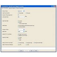
With the Atlantic FIFO buffer clock mode parameter in IP Toolbench, you can
parameterize the receiver in one of the following two clocking structures:
■
■
The MegaCore function uses a common clocking structure for all data path width
variations.
All clocks are asynchronous and paths between the domains can be cut.
The receiver has two primary clock domains. The first clock domain is associated with
the SERDES and logic directly connected to the SPI-4.2 interface; the second clock
domain is associated with the Atlantic interface and the bulk of the receiver logic. The
clock for the first domain is derived from the rdclk of the SPI-4.2 interface. This clock,
rdint_clk, is available as an output from the MegaCore function, and is the output of
the PLL for the ALTLVDS block. For Stratix GX devices, an extra PLL generates the
rdint_clk clock.
For advanced information on the requirements of rxsys_clk, refer to
Optimum Frequency for
In the single clock mode, the Atlantic FIFO buffers are instantiated as single clock
domain buffers, thereby consuming fewer logic resources.
If you select the multiple clock domain mode, the rxsys_clk clock clocks the protocol
logic of the MegaCore function, and the write side of the Atlantic FIFO buffers.
In multiple clock domain mode, an input clock is instantiated for each Atlantic FIFO
buffer in the MegaCore function, which is used for the read side of the buffers. The
naming convention for these input clocks is aN_arxclk. These clocks are inputs to the
MegaCore function and can either be tied together or controlled individually. No
specific frequency requirement is specified for the aN_arxclk clocks, but they should
be fast enough to ensure that the FIFO buffers do not fill, otherwise backpressure is
asserted via the SPI-4.2 status channel.
0
Note to
(1) Worst case, up to MaxBurst1 16-byte units—plus the amount of data in transit due to data and status latency—
MSB
Single clock mode
Multiple clock mode
may still be received, regardless of the current status transmitted.
0
Table
LSB
4–1:
STARVING—FIFO buffer is almost empty. MaxBurst1 credits should be granted in
the far end scheduler.
rxsys_clk.
(1)
Description
Chapter 4: Functional Description—Receiver
December 2010 Altera Corporation
Appendix C,
Clock Structure
Related parts for IP-POSPHY4
Image
Part Number
Description
Manufacturer
Datasheet
Request
R

Part Number:
Description:
IP CORE Renewal Of IP-POSPHY4
Manufacturer:
Altera
Datasheet:

Part Number:
Description:
IP Thermal Transfer Printer With Peel/Present Option
Manufacturer:
BRADY

Part Number:
Description:
CYCLONE II STARTER KIT EP2C20N
Manufacturer:
Altera
Datasheet:


Part Number:
Description:
CPLD, EP610 Family, ECMOS Process, 300 Gates, 16 Macro Cells, 16 Reg., 16 User I/Os, 5V Supply, 35 Speed Grade, 24DIP
Manufacturer:
Altera Corporation
Datasheet:
Part Number:
Description:
CPLD, EP610 Family, ECMOS Process, 300 Gates, 16 Macro Cells, 16 Reg., 16 User I/Os, 5V Supply, 15 Speed Grade, 24DIP
Manufacturer:
Altera Corporation
Datasheet:
Part Number:
Description:
Manufacturer:
Altera Corporation
Datasheet:
Part Number:
Description:
CPLD, EP610 Family, ECMOS Process, 300 Gates, 16 Macro Cells, 16 Reg., 16 User I/Os, 5V Supply, 30 Speed Grade, 24DIP
Manufacturer:
Altera Corporation
Datasheet:
Part Number:
Description:
High-performance, low-power erasable programmable logic devices with 8 macrocells, 10ns
Manufacturer:
Altera Corporation
Datasheet:
Part Number:
Description:
High-performance, low-power erasable programmable logic devices with 8 macrocells, 7ns
Manufacturer:
Altera Corporation
Datasheet:
Part Number:
Description:
Classic EPLD
Manufacturer:
Altera Corporation
Datasheet:
Part Number:
Description:
High-performance, low-power erasable programmable logic devices with 8 macrocells, 10ns
Manufacturer:
Altera Corporation
Datasheet:
Part Number:
Description:
Manufacturer:
Altera Corporation
Datasheet:
Part Number:
Description:
Manufacturer:
Altera Corporation
Datasheet: