SI270X-A-EVB Silicon Laboratories Inc, SI270X-A-EVB Datasheet - Page 31
SI270X-A-EVB
Manufacturer Part Number
SI270X-A-EVB
Description
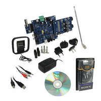
BOARD EVAL FOR SI270X-A
Manufacturer
Silicon Laboratories Inc
Datasheet
1.SI2704-A10-GM.pdf
(46 pages)
Specifications of SI270X-A-EVB
Board Type
Fully Populated
Amplifier Type
Class D
Output Type
2-Channel (Stereo) with Stereo Headphones
Max Output Power X Channels @ Load
5W x 2 @ 3 Ohm
Voltage - Supply
9V
Utilized Ic / Part
SI270X-A
Description/function
Audio Amplifiers
Output Power
5 W
Product
Audio Modules
For Use With/related Products
Si270x
Lead Free Status / RoHS Status
Lead free / RoHS Compliant
Operating Temperature
-
Lead Free Status / Rohs Status
Lead free / RoHS Compliant
Other names
336-1929


Si2704/05/06/07-A10
4.8. Power Supply and Grounding Considerations
Careful attention should be given to the power and ground routing to allow for optimal performance of the Si270x.
The low voltage supplies, V
and V
, should be decoupled with 0.1 µF capacitors soldered as close to the device
DD
IO
as possible so that parasitic inductances are minimized. For the power stage supplies V
and V
, each should
PPL
PPR
be bypassed with a 0.1 µF in ceramic capacitor, located as close to the device as possible, in parallel with a 220 µF
electrolytic capacitor. This allows for optimal filtering in the full frequency spectrum. For detailed information on
board layout considerations and examples refer to “AN470: Si270x Layout Guidelines.”
4.9. Control Interface
2
An I
C-compatible 2-Wire serial port slave interface allows an external controller to send commands, configure
properties, and receive responses from the Si270x. Commands may only be sent after V
and V
supplies are
IO
DD
applied and the RST pin has been released high.
The CLKO pin serves as a configuration boot-strap to select one of two unique addresses to which the Si270x
responds. During reset, if CLKO is pulled low using a 2.2 k resistor connected to ground, then the 7 bit device
address is 1001010 (0x94). If CLKO is left floating, a 22 k internal pull-up within the Si270x causes the 2-Wire to
select a device address of 0011011 (0x36).
A 2-wire transaction begins with the START condition, which occurs when SDIO falls while SCLK is high. Next, the
2-wire master drives an 8-bit control word serially on SDIO which is captured by the device on rising edges of
SCLK. The control word consists of a 7 bit device address followed by a read/write bit (read = 1, write = 0). If the
address matches, the Si270x acknowledges the control word by driving SDIO low on the next falling edge of SCLK.
For write operations, the 2-Wire master sends an eight bit data byte on SDIO following the control word, which is
captured by the device on rising edges of SCLK. The Si270x acknowledges each data byte by driving SDIO low for
one cycle, on the next falling edge of SCLK. The 2-Wire master may write up to eight data bytes during a single
2-wire transaction. The first byte is a command, and the next seven bytes are arguments.
For read operations, after the Si270x has acknowledged the control byte, it drives a data byte on SDIO, changing
the state of SDIO on the falling edge of SCLK. The 2-wire master acknowledges each data byte by driving SDIO
low for one cycle on the next falling edge of SCLK. If a data byte is not acknowledged, the transaction ends. The
2-wire master may read up to 16 data bytes in a single 2-wire transaction. These bytes contain the response data
from the Si270x. A 2-wire transaction ends with the STOP condition, which occurs when SDIO rises while SCLK is
high. For details on timing specifications and diagrams, refer to Table 8 on page 9, Figure 3 on page 11, and
Figure 4 on page 11.
4.10. Programming with Commands
The Si270x provides a simple yet powerful software interface to program configuration and parameter settings. The
device is programmed using commands, arguments, properties, and responses. To perform an action, the user
writes a command byte and associated arguments causing the chip to execute the given command. Commands
control actions, such as powering up the device, shutting down the device, or configure the audio input source.
Arguments are specific to a given command and are used to modify the command. For example, for the
SET_AUDIO_INPUT_MIXER command, arguments are required to set the coefficients of the linear combination of
the sources. Properties are a special command argument used to modify the default chip operation and are
generally configured immediately after power up. Examples of properties include CLOCK_SOURCE and
DEEMPHASIS. A complete list of commands and properties is available in “5. Commands and Properties”.
Responses provide the user information and are returned after a command and associated arguments are sent. At
a minimum, all commands respond with a one-byte status reply indicating interrupt and clear-to-send status
information. Subsequent sections of this data sheet mention many of the commands and properties that are used
to alter different functions. More information on the complete list of programming modes of operation and
properties can be found in the “AN469: Si270x Programming Guide.”
Rev. 0.6
31
Related parts for SI270X-A-EVB
Image
Part Number
Description
Manufacturer
Datasheet
Request
R

Part Number:
Description:
SMD/C°/SINGLE-ENDED OUTPUT SILICON OSCILLATOR
Manufacturer:
Silicon Laboratories Inc
Part Number:
Description:
Manufacturer:
Silicon Laboratories Inc
Datasheet:
Part Number:
Description:
N/A N/A/SI4010 AES KEYFOB DEMO WITH LCD RX
Manufacturer:
Silicon Laboratories Inc
Datasheet:
Part Number:
Description:
N/A N/A/SI4010 SIMPLIFIED KEY FOB DEMO WITH LED RX
Manufacturer:
Silicon Laboratories Inc
Datasheet:
Part Number:
Description:
N/A/-40 TO 85 OC/EZLINK MODULE; F930/4432 HIGH BAND (REV E/B1)
Manufacturer:
Silicon Laboratories Inc
Part Number:
Description:
EZLink Module; F930/4432 Low Band (rev e/B1)
Manufacturer:
Silicon Laboratories Inc
Part Number:
Description:
I°/4460 10 DBM RADIO TEST CARD 434 MHZ
Manufacturer:
Silicon Laboratories Inc
Part Number:
Description:
I°/4461 14 DBM RADIO TEST CARD 868 MHZ
Manufacturer:
Silicon Laboratories Inc
Part Number:
Description:
I°/4463 20 DBM RFSWITCH RADIO TEST CARD 460 MHZ
Manufacturer:
Silicon Laboratories Inc
Part Number:
Description:
I°/4463 20 DBM RADIO TEST CARD 868 MHZ
Manufacturer:
Silicon Laboratories Inc
Part Number:
Description:
I°/4463 27 DBM RADIO TEST CARD 868 MHZ
Manufacturer:
Silicon Laboratories Inc
Part Number:
Description:
I°/4463 SKYWORKS 30 DBM RADIO TEST CARD 915 MHZ
Manufacturer:
Silicon Laboratories Inc
Part Number:
Description:
N/A N/A/-40 TO 85 OC/4463 RFMD 30 DBM RADIO TEST CARD 915 MHZ
Manufacturer:
Silicon Laboratories Inc
Part Number:
Description:
I°/4463 20 DBM RADIO TEST CARD 169 MHZ
Manufacturer:
Silicon Laboratories Inc