E39-C1 Omron, E39-C1 Datasheet
E39-C1
Specifications of E39-C1


Related parts for E39-C1


E39-C1 Summary of contents
Page 1
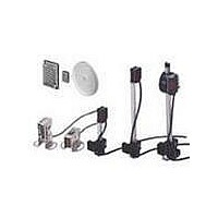
RGB Color Sensor RGB Color Sensor Discriminates Delicate Differences in Color. Best Color Sensor in the Industry. ■ Built-in LED light source ensures long service life and maintenance-free operation. ■ Discriminates differences in color without being influenced by changes in ...
Page 2
... Model E39- (Included) Appearance Application Examples Detection of internal yellow resin plates of battery Discrimination of front and back sides of objects 2 Name Use E39- (Separately sold) Model Appearance Pattern positioning Discrimination of the color order of tissue paper boxes Sensor Mounting DIN-track Mounting Bracket Bracket When mounting the When mounting to the E3MC ...
Page 3
E3MC Specifications Ratings/Characteristics ■ Item Built-in amplifier type E3MC-A@1, E3MC-MA@1 Light source Red (680 nm), green (525 nm), and blue (450 nm) LEDs Sensing distance 60±10 mm (see note 1) Spot diameter 12 dia. Supply voltage VDC±10%, ...
Page 4
E3MC Item Built-in amplifier type E3MC-A@1, E3MC-MA@1 Discriminating color 4 banks selectable (either by bank selection input or by using the SELECT button) selection (1-output Input response time for bank selection max. model only) Indicator Operation indicator (orange ...
Page 5
E3MC Engineering Data Sensing Distance vs. Color Differences (Typical) E3MC-(M)A@@ Sensing Distance vs. Color Differences (Typical) E3MC-(M)X@@ General-purpose Optical Fiber Type ■ Recommended Fiber: Reflective Optical Fiber The following optical fibers are recommended for use with the E3MC-(M)Y@@. Model Sensing ...
Page 6
E3MC Definition of Sensing Distance of a Reflective Fiber The sensing distance of reflective fiber is the sensing distance of the Sensor located obliquely to the sensing object as shown in the following illustration. Set to C mode and standard ...
Page 7
E3MC Available Optical Fibers In addition to the previous recommended optical fibers, the following optical fibers are available for the E3MC-(M)Y@@. Refer to the E3X- NH Datasheet (E258-E1) for the following optical fibers in detail. Optical fibers other than the ...
Page 8
E3MC *Function Switch The following settings are possible in RUN or ADJ mode. In case of 4-output models, all channels are subject to the selection of the follow- ing settings. Each pin of the function switch is factory-set to the ...
Page 9
E3MC E3MC-@41 with PNP Output (1-output Models) Operation indicator (orange) 8-level detection indicator (green) 7-level threshold indicator 4-level bank (red) indicator (green) Main circuit E3MC-M@41 with PNP Output (4-output Models) Operation indicator (orange) 8-level detection indicator (green) 7-level threshold indicator ...
Page 10
E3MC Settings ■ 1-output Models (E3MC-A@@/E3MC-X@@/E3MC-Y@@) 1. Bank Selection Set the Mode Selector to the TEACH mode and then select the BANK using the SELECT button. 2. Color Registration Sensor Registered object Locate the registered object at the detection point ...
Page 11
E3MC 4-output Models (E3MC-MA@@/E3MC-MX@@/E3MC-MY@@) 1. Channel Selection Set the Mode Selector to the TEACH mode and then select the channel using the SELECT button. 2. Color Registration Sensor Registered object Locate the registered object at the detection point and press ...
Page 12
E3MC Detection Level and Indicator ■ Indicator Detection 1 2 level Technical Guide ■ Detection of Metal or Glossy Objects If the E3MC does not detect metal or glossy objects accurately, change the mounting angle of the E3MC so that ...
Page 13
E3MC External Synchronous Input Function ■ The measurement results will be directly output to the control output if the input from the external synchronous input terminal (pink) is set to OFF. The output will hold the previous status if the ...
Page 14
E3MC The following is an example of ladder programming. 00000 TIM000 00100 #XXXX TIM000 00100 END The following is an example of a timing chart of teaching after bank selection. Input detection. ON Remote control input OFF Bank 1 designated. ...
Page 15
E3MC Dimensions Note: All units are in millimeters unless otherwise indicated. RGB Color Sensors ■ E3MC-A@@ E3MC-MA@@ Receiver Emitter E3MC-X@@ E3MC-MX@@ Sensing face (9.1 x 22.9) Receiver Emitter Sensing head (heat-resistive ABS) 3.3-dia. mounting holes Optical axis Mounting Dimensions (Fiber ...
Page 16
... E3MC E3MC-Y@@ E3MC-MY@@ Receiver section Emitter section Accessories (Order Separately) (2-m Cord is Provided with the E3MC) ■ Sensor I/O Connector E39-C1 2M E39-C1 5M 8.8 dia. 10.5 dia. Sensor Mounting Bracket E39-L114 Six, R2.6 Material: Stainless steel (SUS430) 16 Fiber Unit mounting screw Two, 2.4 dia. ...
Page 17
... E3MC DIN-track Mounting Bracket E39-L115 Two, M3 Material: Stainless steel (SUS430) Installation Plug (Sensor I/O Connector) ■ E39-C1 2M E39-C1 5M Internal Wiring Note: Pin 8 is not used. When using the E3MC-@A Mounting Bracket Two, M3 Four, 5.5 dia. Connection Pin no. Wire color Lead wire color ...
Page 18
E3MC Precautions General Do not impose any voltage exceeding the rated voltage on the E3MC, otherwise the E3MC may be damaged. When supplying power to the E3MC, make sure that the polarity of the power is correct, otherwise the E3MC ...
Page 19
E3MC Connection Do not pull the Fiber Unit with force exceeding 9 press the Fiber Unit with force exceeding 29.4 N. The fiber is so thin that the utmost attention will be required to handle the fiber. Do ...
Page 20
... Tighten the M3 screw of the E39-L115 to secure the E39- L115. Removal Loosen the M3 screw of the E39-L115, press the E3MC in the direction indicated by arrow (5) and slide part A in the direction indicated by arrow (6). Then lift up the E3MC in the direction indi- cated by arrow (7) to remove the E3MC with the E39-L115. ...
Page 21
... Please read and understand this catalog before purchasing the products. Please consult your OMRON representative if you have any questions or comments. WARRANTY OMRON's exclusive warranty is that the products are free from defects in materials and workmanship for a period of one year (or other period if specifi ed) from date of sale by OMRON. OMRON MAKES NO WARRANTY OR REPRESENTATION, EXPRESS OR IMPLIED, REGARDING NON-INFRINGEMENT, MERCHANTABILITY, OR FITNESS FOR PARTICULAR PURPOSE OF THE PRODUCTS ...