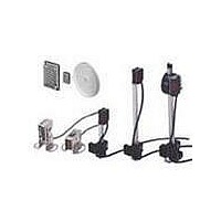
E39-C1 Omron, E39-C1 Datasheet - Page 5

E39-C1
Manufacturer Part Number
E39-C1
Description
E3MC CABLE CONNECTOR 2M
Manufacturer
Omron
Type
Threaded Cylindrical Photoelectric Sensorsr
Specifications of E39-C1
Features
Axial and Radial types
Sensing Distance
7 mm
Amplifier Type
Built In Amplifier
Lead Free Status / RoHS Status
Lead free / RoHS Compliant
Lead Free Status / RoHS Status
Lead free / RoHS Compliant
E3MC
Engineering Data
■
Recommended Fiber: Reflective Optical Fiber
The following optical fibers are recommended for use with the
E3MC-(M)Y@@.
Sensing Distance vs. Color
Differences (Typical)
E3MC-(M)A@@
Sensing Distance vs. Color
Differences (Typical)
E3MC-(M)X@@
E32-DC200
E32-CC200
(see note 2)
E32-D32L
(see note 3)
E32-D11L
General-purpose Optical Fiber Type
Model
5 mm
5 mm
4.5 mm
5 mm
Sensing distance (see note 1)
Angle Characteristics
(Typical)
E3MC-(M)A@@ (X Direction)
Angle Characteristics
(Typical)
E3MC-(M)X@@ (X Direction)
Sensing object:
Blue/Green
30 x 27 mm
Sensing object:
Blue/Green
30 x 27 mm
Note:
1. The E3MC-(M)Y@@ discriminates eleven colors at the
2. The fiber to be inserted into the emitter is indicated with
3. The fiber to be inserted into the emitter is indicated with
Angle (°)
Angle (°)
Detection
level
Detection
level
above distances. For a typical example, nine colors are
discriminated at a sensing distance of 12 mm.
white lines. Insert the amplifier fiber into the lower emit-
ter section.
dotted yellow lines. Insert the amplifier fiber into the
lower emitter section.
E3MC-(M)A@@ (Y Direction)
Angle Characteristics
(When Teaching at an
Inclination of 10°)
E3MC-(M)X@@ (Y Direction)
Angle Characteristics
(When Teaching at an
Inclination of 15°)
Sensing object:
Blue/Green
30 x 27 mm
Sensing object:
Blue/Green
30 x 27 mm
Detection
level
Detection
level
E3MC
Angle (°)
Angle (°)
5


