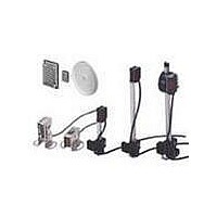
E39-C1 Omron, E39-C1 Datasheet - Page 7

E39-C1
Manufacturer Part Number
E39-C1
Description
E3MC CABLE CONNECTOR 2M
Manufacturer
Omron
Type
Threaded Cylindrical Photoelectric Sensorsr
Specifications of E39-C1
Features
Axial and Radial types
Sensing Distance
7 mm
Amplifier Type
Built In Amplifier
Lead Free Status / RoHS Status
Lead free / RoHS Compliant
Lead Free Status / RoHS Status
Lead free / RoHS Compliant
E3MC
Available Optical Fibers
In addition to the previous recommended optical fibers, the following optical fibers are available for the E3MC-(M)Y@@. Refer to the E3X-
NH Datasheet (E258-E1) for the following optical fibers in detail. Optical fibers other than the following are not available.
Nomenclature
E3MC-A@@ (1-output Models)
E3MC-X@@ (1-output Models)
E3MC-Y@@ (1-output Models)
E3MC-MA@@ (4-output Models)
E3MC-MX@@ (4-output Models)
E3MC-MY@@ (4-output Models)
E32-TC200A
E32-TC200B
E32-TC200C
E32-TC200D
E32-T12L
E32-T14
E32-T11
E32-T11R
Model
lit when the output of each channel is
ON.
Operation Indicator (Orange)
lit when output is ON.
Under mode B, the indicator will be lit when
mode B is started or when the mode
selector is set to TEACH.
Bank Indicator (Green)
Displays selected bank.
TEACH Button
Registers discriminating color.
Operation Indicator (Orange)
lit when output is ON.
Channel Indicator (Orange)
Displays selected channels.
TEACH Button
Registers discriminating color.
Used to check the number of channels that
are indicated by both the operation indicator
and channel indicator.
Through-beam
Through-beam
(R1 fiber)
Sensing method
Not different from
the E32-TC200 in
optical characteris-
tics.
Not different from
the E32-T11L in op-
tical characteristics.
---
---
Remarks
E32-DC200B
E32-DC200C
E32-DC200D
E32-D12
E32-D11
E32-D11R
E32-G14
Model
Detection Level Indicator (Green)
Displays similarity level between registered and
detectable colors.
Threshold Indicator (Red)
Displays threshold level.
SELECT UP Button, SELECT DOWN Button
Bank selection
Threshold adjustment
Mode Selector
Selects TEACH, ADJ, or RUN mode.
Function Switch*
Color discrimination mode selection
Response time selection
OFF-delay timer setting
Conformity/Non-conformity output selection
Detection Level Indicator (Green)
Threshold Indicator (Red)
Displays threshold level.
SELECT UP Button, SELECT DOWN Button
Channel selection
Threshold adjustment
Mode Selector
Selects TEACH, ADJ, or RUN mode.
Function Switch*
Color discrimination mode selection
Response time selection
OFF-delay timer setting
Conformity/Non-conformity output selection
Displays similarity level between registered and
detectable colors.
Reflective
Through-beam
(R1 fiber)
Groove
Sensing method
Not different from the
E32-DC200 in opti-
cal characteristics.
---
---
Remarks
E3MC
7


