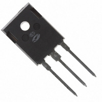
APT25GP120BG Microsemi Power Products Group, APT25GP120BG Datasheet

IGBT 1200V 69A 417W TO247

APT25GP120BG

Manufacturer Part Number
APT25GP120BG
Description
IGBT 1200V 69A 417W TO247
Manufacturer
Microsemi Power Products Group
Series
POWER MOS 7®r
Datasheet

Specifications of APT25GP120BG

Igbt Type
PT
Voltage - Collector Emitter Breakdown (max)
1200V
Vce(on) (max) @ Vge, Ic
3.9V @ 15V, 25A
Current - Collector (ic) (max)
69A
Power - Max
417W
Input Type
Standard
Mounting Type
Through Hole
Package / Case
TO-247
Lead Free Status / RoHS Status
Lead free / RoHS Compliant
Other names
APT25GP120BGMI
APT25GP120BGMI

Available stocks

Company
Part Number
Manufacturer
Quantity
Price
Part Number:
APT25GP120BG
Manufacturer:
Microsemi Power Products Group
Quantity:
135
A new generation of high voltage power IGBTs. Using punch-through
technology and a proprietary metal gate, this IGBT has been optimized for
very fast switching, making it ideal for high frequency, high voltage switch-
mode power supplies and tail current sensitive applications. In many cases,
the POWER MOS 7
MOSFET.
• Low Conduction Loss
• Low Gate Charge
• Ultrafast Tail Current shutoff
MAXIMUM RATINGS
STATIC ELECTRICAL CHARACTERISTICS
Symbol
RBSOA
T
Symbol
V
V
BV
V
V
J
GE(TH)
CE(ON)
I
V
I
I
,T
I
I
P
GEM
CES
GES
CES
T
CM
C1
C2
GE
CES
D
L
STG
CAUTION: These Devices are Sensitive to Electrostatic Discharge. Proper Handling Procedures Should Be Followed.
Parameter
Collector-Emitter Voltage
Gate-Emitter Voltage
Gate-Emitter Voltage Transient
Continuous Collector Current @ T
Pulsed Collector Current
Reverse Bias Safe Operating Area @ T
Total Power Dissipation
Operating and Storage Junction Temperature Range
Max. Lead Temp. for Soldering: 0.063" from Case for 10 Sec.
Characteristic / Test Conditions
Collector-Emitter Breakdown Voltage (V
Gate Threshold Voltage (V
Collector-Emitter On Voltage (V
Collector Cut-off Current (V
Gate-Emitter Leakage Current (V
POWER MOS 7
®
IGBT provides a lower cost alternative to a Power
1
CE
CE
CE
APT Website - http://www.advancedpower.com
@ T
= V
= 1200V, V
= 1200V, V
GE
GE
• 50 kHz operation @ 800V, 19A
• RBSOA Rated
• 100 kHz operation @ 800V,11A
C
C
C
GE
GE
= 25°C
= 15V, I
= 15V, I
= 25°C
= 110°C
, I
= ±20V)
C
J
= 1mA, T
= 150°C
GE
GE
GE
®
C
C
= 0V, I
= 25A, T
= 25A, T
= 0V, T
= 0V, T
IGBT
j
C
= 25°C)
j
= 250µA)
j
= 25°C)
= 125°C)
j
j
= 25°C)
= 125°C)
All Ratings: T
2
2
APT25GP120B
C
= 25°C unless otherwise specified.
1200
MIN
3
APT25GP120B
90A @ 960V
-55 to 150
G
TYP
4.5
3.3
3.0
1200
±20
±30
C
417
300
69
33
90
E
TO-247
±100
2500
MAX
250
3.9
6
G
1200V
Amps
Watts
UNIT
UNIT
Volts
Volts
µA
nA
°C
C
E

Related parts for APT25GP120BG

APT25GP120BG Summary of contents

Page 1

POWER MOS 7 A new generation of high voltage power IGBTs. Using punch-through technology and a proprietary metal gate, this IGBT has been optimized for very fast switching, making it ideal for high frequency, high voltage switch- mode power supplies ...

Page 2

DYNAMIC CHARACTERISTICS Symbol Characteristic C IInput Capacitance ies C Output Capacitance oes C Reverse Transfer Capacitance res V Gate-to-Emitter Plateau Voltage GEP 3 Q Total Gate Charge g Q Gate-Emitter Charge ge Q Gate-Collector ("Miller ") Charge gc RBSOA Reverse ...

Page 3

TYPICAL PERFORMANCE CURVES 15V. 250µs PULSE TEST <0.5 % DUTY CYCLE =125° COLLECTER-TO-EMITTER VOLTAGE (V) CE FIGURE 1, Output Characteristics(V 100 250µs ...

Page 4

V = 10V 15V 600V 25°C, T =125° 100 µ ...

Page 5

TYPICAL PERFORMANCE CURVES 10,000 5,000 1,000 500 100 COLLECTOR-TO-EMITTER VOLTAGE (VOLTS) CE Figure 17, Capacitance vs Collector-To-Emitter Voltage 0.35 0.30 0.9 0.25 0.7 0.20 0.5 0.15 0.3 0.10 0.05 0.1 0. ...

Page 6

APT15DF120 D.U.T. Figure 21, Inductive Switching Test Circuit 90 d(off) f 90% 10% Switching Energy Figure 23, Turn-off Switching Waveforms and Definitions APT’s products are covered by one or more of ...

Related keywords