BSH111,215 NXP Semiconductors, BSH111,215 Datasheet - Page 2
BSH111,215
Manufacturer Part Number
BSH111,215
Description
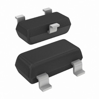
MOSFET N-CH 55V 335MA SOT-23
Manufacturer
NXP Semiconductors
Series
TrenchMOS™r
Type
Power MOSFETr
Datasheet
1.BSH111215.pdf
(13 pages)
Specifications of BSH111,215
Package / Case
SOT-23-3, TO-236-3, Micro3™, SSD3, SST3
Fet Type
MOSFET N-Channel, Metal Oxide
Fet Feature
Logic Level Gate
Rds On (max) @ Id, Vgs
4 Ohm @ 500mA, 4.5V
Drain To Source Voltage (vdss)
55V
Current - Continuous Drain (id) @ 25° C
335mA
Vgs(th) (max) @ Id
1.3V @ 1mA
Gate Charge (qg) @ Vgs
1nC @ 10V
Input Capacitance (ciss) @ Vds
40pF @ 10V
Power - Max
830mW
Mounting Type
Surface Mount
Minimum Operating Temperature
- 65 C
Configuration
Single
Transistor Polarity
N-Channel
Resistance Drain-source Rds (on)
4 Ohm @ 4.5 V
Gate Charge Qg
0.05 nC
Forward Transconductance Gfs (max / Min)
380 S
Drain-source Breakdown Voltage
55 V
Gate-source Breakdown Voltage
+/- 10 V
Continuous Drain Current
0.335 A
Power Dissipation
830 mW
Maximum Operating Temperature
+ 150 C
Mounting Style
SMD/SMT
Number Of Elements
1
Polarity
N
Channel Mode
Enhancement
Drain-source On-res
4Ohm
Drain-source On-volt
55V
Gate-source Voltage (max)
±10V
Operating Temp Range
-65C to 150C
Operating Temperature Classification
Military
Mounting
Surface Mount
Pin Count
3
Package Type
TO-236AB
Lead Free Status / RoHS Status
Lead free / RoHS Compliant
Lead Free Status / RoHS Status
Lead free / RoHS Compliant, Lead free / RoHS Compliant
Other names
568-1657-2
934056036215
BSH111 T/R
934056036215
BSH111 T/R


Philips Semiconductors
5. Quick reference data
Table 2:
6. Limiting values
Table 3:
In accordance with the Absolute Maximum Rating System (IEC 60134).
9397 750 09629
Product data
Symbol Parameter
V
I
P
T
R
Symbol Parameter
V
V
V
I
I
P
T
T
Source-drain diode
I
I
D
D
DM
S
SM
DS
tot
j
DS
DGR
GS
tot
stg
j
DSon
drain-source voltage (DC)
drain current (DC)
total power dissipation
junction temperature
drain-source on-state resistance
drain-source voltage (DC)
drain-gate voltage (DC)
gate-source voltage
drain current (DC)
peak drain current
total power dissipation
storage temperature
junction temperature
source (diode forward) current (DC)
peak source (diode forward) current
Quick reference data
Limiting values
Conditions
25 C
T
T
V
V
V
Conditions
25 C
25 C
T
Figure 2
T
T
Figure 3
T
T
T
Rev. 02 — 26 April 2002
sp
sp
GS
GS
GS
sp
sp
sp
sp
sp
sp
= 25 C; V
= 25 C
= 25 C; V
= 100 C; V
= 25 C; pulsed; t
= 25 C;
= 25 C
= 25 C; pulsed; t
= 4.5 V; I
= 2.5 V; I
= 1.8 V; I
T
T
T
and
j
j
j
N-channel enhancement mode field-effect transistor
150 C
150 C
150 C; R
Figure 1
3
D
D
D
GS
GS
= 500 mA
= 75 mA
= 75 mA
GS
= 4.5 V
= 4.5 V;
= 4.5 V;
p
p
GS
10 s;
10 s
= 20 k
Figure 2
© Koninklijke Philips Electronics N.V. 2002. All rights reserved.
Typ
-
-
-
-
2.3
2.4
3.1
Min
-
-
-
-
-
-
-
-
-
65
65
Max
55
335
0.83
150
4.0
5.0
8.0
Max
55
55
335
212
1.3
0.83
+150
+150
335
1.3
BSH111
10
Unit
V
mA
W
Unit
V
V
V
mA
mA
A
W
mA
A
C
C
C
2 of 13
Related parts for BSH111,215
Image
Part Number
Description
Manufacturer
Datasheet
Request
R

Part Number:
Description:
Extremely low level N-channel enhancement mode Field-Effect Transistor (FET) in a plastic package using TrenchMOS technology
Manufacturer:
NXP Semiconductors
Datasheet:

Part Number:
Description:
Bsh111 N-channel Enhancement Mode Field-effect Transistor
Manufacturer:
NXP Semiconductors
Datasheet:

Part Number:
Description:
MOSFET N-CH 55V 0.335A SOT23
Manufacturer:
NXP Semiconductors
Datasheet:
Part Number:
Description:
NXP Semiconductors designed the LPC2420/2460 microcontroller around a 16-bit/32-bitARM7TDMI-S CPU core with real-time debug interfaces that include both JTAG andembedded trace
Manufacturer:
NXP Semiconductors
Datasheet:

Part Number:
Description:
NXP Semiconductors designed the LPC2458 microcontroller around a 16-bit/32-bitARM7TDMI-S CPU core with real-time debug interfaces that include both JTAG andembedded trace
Manufacturer:
NXP Semiconductors
Datasheet:
Part Number:
Description:
NXP Semiconductors designed the LPC2468 microcontroller around a 16-bit/32-bitARM7TDMI-S CPU core with real-time debug interfaces that include both JTAG andembedded trace
Manufacturer:
NXP Semiconductors
Datasheet:
Part Number:
Description:
NXP Semiconductors designed the LPC2470 microcontroller, powered by theARM7TDMI-S core, to be a highly integrated microcontroller for a wide range ofapplications that require advanced communications and high quality graphic displays
Manufacturer:
NXP Semiconductors
Datasheet:
Part Number:
Description:
NXP Semiconductors designed the LPC2478 microcontroller, powered by theARM7TDMI-S core, to be a highly integrated microcontroller for a wide range ofapplications that require advanced communications and high quality graphic displays
Manufacturer:
NXP Semiconductors
Datasheet:
Part Number:
Description:
The Philips Semiconductors XA (eXtended Architecture) family of 16-bit single-chip microcontrollers is powerful enough to easily handle the requirements of high performance embedded applications, yet inexpensive enough to compete in the market for hi
Manufacturer:
NXP Semiconductors
Datasheet:
Part Number:
Description:
The XA-S3 device is a member of Philips Semiconductors? XA(eXtended Architecture) family of high performance 16-bitsingle-chip microcontrollers
Manufacturer:
NXP Semiconductors
Datasheet:

Part Number:
Description:
The NXP BlueStreak LH75401/LH75411 family consists of two low-cost 16/32-bit System-on-Chip (SoC) devices
Manufacturer:
NXP Semiconductors
Datasheet:
Part Number:
Description:
The NXP LPC3130/3131 combine an 180 MHz ARM926EJ-S CPU core, high-speed USB2
Manufacturer:
NXP Semiconductors
Datasheet:
Part Number:
Description:
The NXP LPC3141 combine a 270 MHz ARM926EJ-S CPU core, High-speed USB 2
Manufacturer:
NXP Semiconductors
Part Number:
Description:
The NXP LPC3143 combine a 270 MHz ARM926EJ-S CPU core, High-speed USB 2
Manufacturer:
NXP Semiconductors