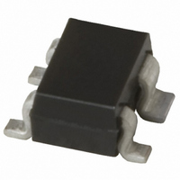
BFP 540 E6327 Infineon Technologies, BFP 540 E6327 Datasheet - Page 3

BFP 540 E6327
Manufacturer Part Number
BFP 540 E6327
Description
TRANSISTOR RF NPN 4.5V SOT-343
Manufacturer
Infineon Technologies
Datasheet
1.BFP_540_E6327.pdf
(10 pages)
Specifications of BFP 540 E6327
Package / Case
SC-70-4, SC-82-4, SOT-323-4, SOT-343
Transistor Type
NPN
Voltage - Collector Emitter Breakdown (max)
5V
Frequency - Transition
30GHz
Noise Figure (db Typ @ F)
0.9dB ~ 1.4dB @ 1.8GHz
Gain
21.5dB
Power - Max
250mW
Dc Current Gain (hfe) (min) @ Ic, Vce
50 @ 20mA, 3.5V
Current - Collector (ic) (max)
80mA
Mounting Type
Surface Mount
Dc Collector/base Gain Hfe Min
50 @ 20mA @ 3.5V
Minimum Operating Temperature
- 65 C
Mounting Style
SMD/SMT
Configuration
Single Dual Emitter
Transistor Polarity
NPN
Maximum Operating Frequency
30000 MHz (Typ)
Collector- Emitter Voltage Vceo Max
4.5 V
Emitter- Base Voltage Vebo
1 V
Continuous Collector Current
0.08 A
Power Dissipation
250 mW
Maximum Operating Temperature
+ 150 C
Lead Free Status / RoHS Status
Lead free / RoHS Compliant
Lead Free Status / RoHS Status
Lead free / RoHS Compliant, Lead free / RoHS Compliant
Other names
BFP 540 E6327
BFP540E6327INTR
BFP540E6327XT
SP000012602
BFP540E6327INTR
BFP540E6327XT
SP000012602
1
2
Termination used for this measurement is 50 Ω from 0.1 MHz to 6 GHz
Electrical Characteristics at T
Parameter
AC Characteristics (verified by random sampling)
Transition frequency
I
Collector-base capacitance
V
emitter grounded
Collector emitter capacitance
V
base grounded
Emitter-base capacitance
V
collector grounded
Noise figure
I
I
Power gain, maximum stable
I
Z
Power gain, maximum available
I
Z
Transducer gain
I
f = 1.8 GHz
f = 3 GHz
Third order intercept point at output
V
1dB Compression point at output
I
C
C
C
C
C
C
C
G ma = |S 21e / S 12e | (k-(k²-1) 1/2 ), G ms = |S 21e / S 12e |
IP3 value depends on termination of all intermodulation frequency components.
L
L
CB
CE
EB
CE
= 50 mA, V
= 5 mA, V
= 5 mA, V
= 20 mA, V
= 20 mA, V
= 20 mA, V
= 20 mA, V
= Z
= Z
= 0.5 V, f = 1 MHz, V
= 2 V, f = 1 MHz, V
= 2 V, f = 1 MHz, V
= 2 V, I
Lopt
Lopt
, f = 3 GHz
, f = 1.8 GHz
C
CE
CE
CE
CE
CE
CE
= 20 mA, Z
CE
= 2 V, f = 1.8 GHz, Z
= 2 V, f = 3 GHz, Z
= 4 V, f = 1 GHz
= 2 V, Z
= 2 V, Z
= 2 V, Z
= 2 V, Z
BE
BE
S
S
S
S
S
CB
=Z
=Z
= 0 ,
= 0 ,
= Z
= Z
= Z
= 0 ,
1)
L
L
=50 Ω
=50 Ω
Sopt
Sopt
L
A
1)
= 50 Ω ,
= 25°C, unless otherwise specified
,
,
S
2)
,
,
f
f
S
= Z
=
=
= Z
1
1
Sopt
.
.
8 GHz
8 GHz
Sopt
3
Symbol
f
C
C
C
F
G
G
|S
IP
P
T
-1dB
cb
ce
eb
ms
ma
21e
3
|
2
min.
21
16
-
-
-
-
-
-
-
-
-
-
Values
21.5
18.5
14.5
24.5
0.14
0.33
0.65
typ.
0.9
1.3
30
16
11
2009-12-04
max.
0.24
1.4
-
-
-
-
-
-
-
-
-
-
BFP540
Unit
GHz
pF
dB
dB
dB
dB
dBm


