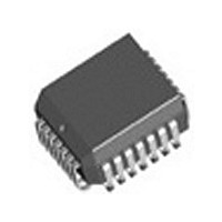
82V1671J IDT, Integrated Device Technology Inc, 82V1671J Datasheet - Page 23

82V1671J
Manufacturer Part Number
82V1671J
Description
Manufacturer
IDT, Integrated Device Technology Inc
Datasheet
1.82V1671J.pdf
(107 pages)
Specifications of 82V1671J
Number Of Channels
4
On-hook Transmission
Yes
Polarity Reversal
Yes
On-chip Ring Relay Driver
Yes
Operating Supply Voltage (typ)
3.3V
Operating Temp Range
-40C to 85C
Package Type
PLCC
Operating Temperature Classification
Industrial
Pin Count
28
Mounting
Surface Mount
Operating Current
95mA
Operating Supply Voltage (max)
3.465V
Operating Supply Voltage (min)
3.135V
Lead Free Status / RoHS Status
Not Compliant
3.4
ringing modes to meet different requirements.
3.4.1
3.4.1.1
generate balanced sinusoidal ringing signal without external
components. The frequency, amplitude and DC offset of the ringing
signal are programmable. In addition, the ring trip detection can be
performed internally by programming the ring trip threshold.
switched to the higher battery (VBH) for ringing generation. The ringing
signal generated by the CODEC is sent to the RSLIC via the DCP and
3.4.1.2
state during ringing, the ringing signal must be removed from the
subscriber line before normal speech begins. The recognition of an off-
hook state during ringing, together with the removal of the ringing signal,
is commonly referred to as ring trip. Depending on the application
requirements, the RSLIC-CODEC chipset offers two different ring trip
methods for internal ringing mode, they are DC ring trip detection and
AC ring trip detection, as selected by the RT_SEL bit in LREG7.
voltage together with the ringing signal, a transversal DC loop current
starts to flow when the subscriber goes off-hook. The RSLIC senses the
DC current and supplies the corresponding sensed voltage to the
CODEC via the VTAC pin. The CODEC continuously integrates this
voltage over one ringing period without rectifying. The result represents
the DC component of the ring current. If the DC component exceeds the
programmed DC ring trip threshold, the corresponding HK[n] bit (n = 0 to
3 are for Channel 1 to 4 respectively) in register GREG26 will be set to 1
to indicate that the loop has been off-hook. An interrupt will be generated
RSLIC & CODEC CHIPSET
The RSLIC-CODEC chipset supports both internal and external
The chipset provides a built-in ring generator per channel that can
If internal ringing mode is selected, the RSLIC will be automatically
• DC Ring Trip Detection
Most applications use DC ring trip detection. By applying a DC offset
Once the subscriber has switched from on-hook state to off-hook
RING AND RING TRIP
INTERNAL RINGING MODE
Internal Ringing Generation
Ring Trip Detection In Internal Ringing Mode
V
V
DROP.T
DROP.R
V
DC.RING
Tip Line
Ring Line
Figure - 11 Internal Balanced Ringing
V
V
Tp
Rp
V
V
T
R
23
V
RING.PP
DCN pins and further fed to the subscriber line by the RSLIC. Refer to
Figure - 49 on page 104
mode to Internal Ringing (the CODEC is set to the RING mode and the
RSLIC is set to Internal Ringing mode, refer to
Next, calculate the coefficients of the ringing frequency, amplitude and
DC offset and load the coefficients to the Coe-RAM (the calculation is
performed by a software (Cal74) provided by IDT. When users input the
frequency, amplitude and offset values, Cal74 will calculate the
coefficients automatically). Then, the ringing generation will be
controlled by the RING_EN bit in LREG7. In order to reduce noise and
crosstalk on adjacent lines, the ringing signal will automatically start at a
zero-crossing after the RING_EN bit is set to 1 and stop at zero-crossing
after the RING_EN bit is set to 0.
chipset.
simultaneously if the corresponding mask bit HK_M[n] is set to 0.
reliable. Even with very long and noisy lines the off-hook condition can
reliably be detected within two ringing period by the DC ring trip. The DC
ring trip method is selected by setting the RT_SEL bit in LREG7 to 1.
The DC offset voltage is programmed by the RingOffset in the coefficient
RAM. See
signal will stop immediately at zero-crossing. But the RING_EN bit will
not be cleared to 0 automatically; it should eventually be cleared by
software. This automatic ring trip function speeds up the response to off-
hook for time critical applications.
ringing signal to increase the achievable voltage amplitude for a given
supply voltage. The AC ring trip detection without DC offset is realized
by rectifying sensed ring current signal, integrating it over one ringing
signal period and comparing the result with the programmed AC ring trip
threshold. If the threshold is exceeded, the corresponding bit HK[n] (n =
0 to 3 are for Channel 1 to 4 respectively) in register GREG26 will be set
To generate a ringing signal, users should first set the operating
Figure - 11
Most of the applications use DC ring trip detection because it is very
In DC ring trip mode, when an off-hook event is detected, the ringing
• AC Ring Trip Detection
For short loop applications, the DC offset can be removed from the
= V
Tp
Table - 2
- V
Rp
shows a balanced ringing signal generated by the
for detailed information.
RSLIC
BGND
VBH
IDT82V1671/IDT82V1671A, IDT82V1074
for an application circuit using internal ringing.
Table - 3
for details).


