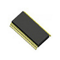
ICS932S421BGLF IDT, Integrated Device Technology Inc, ICS932S421BGLF Datasheet - Page 19

ICS932S421BGLF
Manufacturer Part Number
ICS932S421BGLF
Description
IC PCIE GEN2 MAIN CLOCK 56-TSSOP
Manufacturer
IDT, Integrated Device Technology Inc
Type
Clock Generatorr
Series
-r
Datasheet
1.ICS932S421BFLFT.pdf
(23 pages)
Specifications of ICS932S421BGLF
Frequency - Max
400MHz
Voltage - Supply
3.135 V ~ 3.465 V
Operating Temperature
0°C ~ 70°C
Mounting Type
Surface Mount
Package / Case
56-TSSOP
Frequency-max
400MHz
Number Of Elements
3
Supply Current
350mA
Pll Input Freq (min)
14.31818MHz
Operating Supply Voltage (typ)
3.3V
Operating Temp Range
0C to 70C
Package Type
TSSOP
Output Frequency Range
33.33 to 400MHz
Operating Supply Voltage (min)
3.135V
Operating Supply Voltage (max)
3.465V
Operating Temperature Classification
Commercial
Pin Count
56
Input
-
Output
-
Lead Free Status / RoHS Status
Lead free / RoHS Compliant
Output
-
Input
-
Lead Free Status / Rohs Status
Compliant
Other names
932S421BGLF
Available stocks
Company
Part Number
Manufacturer
Quantity
Price
Company:
Part Number:
ICS932S421BGLF
Manufacturer:
ICS
Quantity:
3 078
Part Number:
ICS932S421BGLFT
Manufacturer:
ICS
Quantity:
20 000
PD Assertion
PD should be sampled high by 2 consecutive CPU# rising edges before stopping clocks. All single ended clocks will be
held low on their next high to low transition.
All differential clocks will be held high on the next high to low transition of the complimentary clock. If the control register
determining to drive mode is set to 'tri-state', the differential pair will be stopped in tri-state mode, undriven.
When the drive mode corresponding to the CPU or SRC clock of interest is set to '0' the true clock will be driven high at 2 x
Iref and the complementary clock will be tristated. If the control register is programmed to '1' both clocks will be tristated.
See SMBus Bytes 4 and 5 for additional information.
PD, Power Down
PD is an asynchronous active high input used to shut off all clocks cleanly prior to system power down.
When PD is asserted, all clocks will be driven low before turning off the VCO. All clocks will start without glitches when PD is
de-asserted.
Notes:
1. Refer to SMBus Byte 4 for additional information.
IDT
CPU, SRC and PCI Divider Ratios
10
11
12
13
14
15
ICS932S421B
PCIe Gen2 and QPI Clock for Intel-Based Servers
0
1
2
3
4
5
6
7
8
9
TM
P
0
1
D
PCIe Gen2 and QPI Clock for Intel-Based Servers
Div(3:0)
0000
0001
0010
0011
0100
0101
0110
0111
1000
1001
1010
1011
1100
1101
1110
1111
I
e r
N
F
C
r o
* f
o l
P
m
t a
U
2
l a
r o
Divider
120
N
C
15
10
30
12
20
60
16
24
40
2
3
5
4
6
8
F
r o
P
o l
CPU#, 133MHz
SRC#, 100MHz
REF, 14.31818
U
CPU, 133MHz
SRC, 100MHz
m
t a
USB, 48MHz
PCI, 33MHz
l a
#
r o
PD
N
I
e r
S
r o
F
R
* f
m
o l
C
t a
l a
2
N
S
F
r o
R
o l
C
m
t a
#
l a
P
3
C
3
L
F I
M
o
P /
w
H
z
I C
19
4
U
8
L
M
o
S
w
B
H
REF Drive Strength Functionality
Byte6,
z
bit 4
0
1
1
1
1
1
4
3 .
10, bit 1
R
L
1
Byte
o
E
8
X
w
0
0
1
1
F
M
H
z
Byte 10,
N
bit 0
o
X
0
1
0
1
e t
1
1
REF1
1x
1x
1x
2x
2x
REF0
1340G—01/26/10
1x
1x
2x
1x
2x


