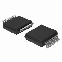
74LV4799DB,118 NXP Semiconductors, 74LV4799DB,118 Datasheet - Page 9

74LV4799DB,118
Manufacturer Part Number
74LV4799DB,118
Description
IC TIMER NICD/NIMH CHRGR 16SSOP
Manufacturer
NXP Semiconductors
Type
Timer Controlr
Series
74LVr
Datasheet
1.74LV4799SD118.pdf
(18 pages)
Specifications of 74LV4799DB,118
Package / Case
16-SSOP
Frequency
100kHz
Voltage - Supply
0.9 V ~ 6 V
Current - Supply
36µA
Operating Temperature
0°C ~ 70°C
Supply Voltage (max)
6 V
Supply Voltage (min)
0.9 V
Maximum Operating Temperature
+ 70 C
Minimum Operating Temperature
0 C
Mounting Style
SMD/SMT
Lead Free Status / RoHS Status
Lead free / RoHS Compliant
Count
-
Lead Free Status / RoHS Status
Lead free / RoHS Compliant, Lead free / RoHS Compliant
Other names
74LV4799DB-T
74LV4799DB-T
935175040118
74LV4799DB-T
935175040118
1. The oscillator frequency can be calculated by: f + 0.36
2. During blinking.
3. An output signal of four periods will appear in case of discharged batteries and DIS is switched HIGH.
Philips Semiconductors
AC CHARACTERISTICS
GND = 0V; t
NOTES:
APPLICATION INFORMATION
Oscillator.
The frequency will be determined by the external components R
expressions: f +
R
R
R
The charge, discharge and self-discharge times can be calculated as follows:
In the trickle charge mode, the average charge current will be reduced by a factor:
External components range
1998 Apr 20
Charge time + 2
SYMBOL
C
D
S
Timer for NiCd and NiMH chargers
SYMBOL
f
f
f
f
and C1 determine the charge time.
and C1 determine the discharge time.
and C1 determine the self-charge time.
MOLLI
MOLLI
i(
i(max)
i( i )
i(min)
t
t
R
R
LED
LED
d b
deb
C
C
f
f
R
R
C1
C1
/R
/R
S
S
)
D
D
r
Oscillator frequency spread
Oscillator frequency s read
Duty factor at pin 1
Duty factor at in 1
Duty factor at pin 6
Duty factor at in 6
Debounce suppression at pin 9
Debounce su ression at in 9
Maximum frequency at power
sense input
Minimum frequency at power
sense input
= t
f
Resistor range
Resistor range
Resistor range
Resistor range
Capacitor range
Ca acitor range
f
C
R
22
2.5ns; C
C
; Discharge time + 2
0.36
PARAMETER
PARAMETER
C1
q
q
; f +
L
= 50pF
y
y
R
D
0.36
C1
f
; f +
18
D
; Self-discharge time + 2
V
R
CC
1.0
6.0
1.0
6.0
1.0
6.0
1.0
6.0
1.0
6.0
1.0
6.0
S
0.36
V
(V)
CC
1.0
2.0
4.5
6.0
1.0
2.0
4.5
6.0
1.0
2.0
4.5
6.0
C1
(V)
R
Any resistor or capacitor according to
the application information, see note 1
See Note 2
See Note 2
See Note 3
See Note 3
.
y
C1
TEST CONDITIONS
TEST CONDITIONS
TEST CONDITIONS
TEST CONDITIONS
C
, R
D
f
V
, R
27
S
1
9
S
, and C
C1 = 0 22 F
C1 = 0.22 F
C1 = 0 22 F
C1 = 0.22 F
1
. The frequencies can be calculated by the following
1 )
OTHER
3 x R
4 x R
1
g
S
C
5.360
1.150
0.562
0.511
42.20
9.09
4.22
3.32
MIN
MIN
100
100
–11
–9
–
–
–
–
–
–
TYP
+25
T
–4
–2
50
50
50
50
67
65
amb
TYP
+25
T
amb
( C)
MAX
+3
+5
50
50
( C)
no limit
no limit
no limit
no limit
MAX
100
100
100
100
825
825
825
825
MIN
Product specification
74LV4799
0 to +70
MAX
UNIT
kW
kW
kW
kW
kW
kW
kW
kW
pF
pF
F
F
UNIT
kHz
kHz
ms
ms
Hz
Hz
%
%
%
%
%
%


