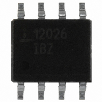
ISL12026IBZ Intersil, ISL12026IBZ Datasheet - Page 5

ISL12026IBZ
Manufacturer Part Number
ISL12026IBZ
Description
IC RTC/CALENDAR EEPROM 8-SOIC
Manufacturer
Intersil
Type
Clock/Calendar/EEPROMr
Specifications of ISL12026IBZ
Memory Size
4K (512 x 8)
Time Format
HH:MM:SS (12/24 hr)
Date Format
YY-MM-DD-dd
Interface
I²C, 2-Wire Serial
Voltage - Supply
2.7 V ~ 5.5 V
Operating Temperature
-40°C ~ 85°C
Mounting Type
Surface Mount
Package / Case
8-SOIC (3.9mm Width)
Clock Format
HH
Clock Ic Type
RTC
Interface Type
I2C, Serial
Memory Configuration
512 X 8
Supply Voltage Range
2.7V To 5.5V
Digital Ic Case Style
SOIC
Rohs Compliant
Yes
Lead Free Status / RoHS Status
Lead free / RoHS Compliant
Available stocks
Company
Part Number
Manufacturer
Quantity
Price
Company:
Part Number:
ISL12026IBZ
Manufacturer:
INTELSEL
Quantity:
60
Part Number:
ISL12026IBZ
Manufacturer:
INTERSIL
Quantity:
20 000
Part Number:
ISL12026IBZ-T
Manufacturer:
INTERSIL
Quantity:
20 000
AC Electrical Specifications
NOTES:
10. Bit BSW = 0 (Standard Mode), ATR = 00h, V
12. In order to ensure proper timekeeping, the V
13. Parameter is not 100% tested.
14. t
15. These are I
16. Compliance to datasheet limits is assured by one or more methods: production test, characterization and/or design.
Timing Diagrams
Bus Timing
11. Specified at +25°C.
7. IRQ/F
8. V
9. V
SYMBOL
t
t
SU:STO
HD:STO
(OUTPUT TIMING)
Cpin
R
sequence of a serial interface Write operation, to the end of the self-timed internal non-volatile write cycle.
t
t
WC
Cb
WC
DH
t
t
IL
DD
(INPUT TIMING)
R
PU
F
= V
is the minimum cycle time to be allowed for any non-volatile Write by the user, it is the time from valid STOP condition at the end of Write
> V
OUT
DD
BAT
STOP Condition Set-up Time
STOP Condition Hold Time for
Read or Volatile Only Write
Output Data Hold Time
SDA and SCL Pin Capacitance
Non-volatile Write Cycle Time
SDA and SCL Rise Time
SDA and SCL Fall Time
Capacitive Loading of SDA or SCL Total on-chip and off-chip
SDA and SCL Bus Pull-up Resistor
Off-chip
Inactive.
x 0.1, V
2
C specific parameters and are not directly tested, however they are used during device testing to validate device specification.
SDA
SDA
SCL
+V
BATHYS
t
SU:STA
IH
PARAMETER
= V
DD
x 0.9, f
5
t
HD:STA
SCL
(Continued)
= 400kHz
t
F
t
DD SR-
BAT
SU:DAT
From SCL rising edge crossing 70%
of V
30% of V
From SDA rising edge to SCL falling
edge. Both crossing 70% of V
From SCL falling edge crossing 30%
of V
70% of V
From 30% to 70% of V
From 70% to 30% of V
Maximum is determined by t
For Cb = 400pF, max is about
2kΩ~2.5kΩ.
For Cb = 40pF, max is about
15kΩ~20kΩ
≥1.8V
DD
DD
specification must be followed.
ISL12026, ISL12026A
, to SDA rising edge crossing
, until SDA enters the 30% to
TEST CONDITIONS
DD
DD
t
HIGH
.
window.
t
LOW
DD
DD
R
t
HD:DAT
and t
DD
.
F
.
20 + 0.1xCb
20 +0.1xCb
(Note 16)
t
R
MIN
600
600
10
0
1
t
AA
t
DH
TYP
12
(Note 16)
MAX
300
300
400
10
20
t
BUF
UNITS
t
SU:STO
ms
pF
pF
kΩ
ns
ns
ns
ns
ns
t
HD:STO
November 30, 2010
NOTES
FN8231.9
14
15
15
15


