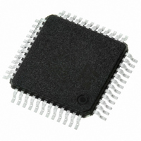
STLC7550TQF7TR STMicroelectronics, STLC7550TQF7TR Datasheet - Page 7

STLC7550TQF7TR
Manufacturer Part Number
STLC7550TQF7TR
Description
IC ANALOG FRONT END LV 48-TQFP
Manufacturer
STMicroelectronics
Datasheet
1.E-STLC7550TQF7.pdf
(24 pages)
Specifications of STLC7550TQF7TR
Number Of Bits
16
Number Of Channels
1
Power (watts)
30mW
Voltage - Supply, Analog
3V
Voltage - Supply, Digital
3V
Package / Case
48-TQFP, 48-VQFP
Lead Free Status / RoHS Status
Lead free / RoHS Compliant
Available stocks
Company
Part Number
Manufacturer
Quantity
Price
Company:
Part Number:
STLC7550TQF7TR
Manufacturer:
STMicroelectronics
Quantity:
10 000
STLC7550
than two times the sampling frequency (FS), so that the combined frequency response of
both the internal and external filters is flat in the passband. The attenuator of the last output
stage can be programmed to 0dB, 6dB or infinite.
Non-inverting Analog Input (IN+)
This pin is the differential non-inverting ADC input.
Inverting Analog Input (IN-)
This pin is the differential inverting ADC input. These analog inputs (IN+, IN-) are presented
to the Sigma-Delta modulator. The analog input peak-topeak differential signal range must
be less than 2 x V
The cut-off frequency of the filter must be lower than one half the oversampling frequency.
These filters should be set as close as possible to the IN+ and IN- pins. The gain of the first
stage is programmable (see
Non-inverting Auxiliary Analog Input (AUX IN+)
This pin is the differential non-inverting auxiliary ADC input. The characteristics are same as
the IN+ input.
Inverting Auxiliary Analog Input (AUX IN-)
This pin is the differential inverting auxiliary ADC input. The characteristics are same as the
IN- input. The input pair (IN+/IN- or AUX IN+/AUX IN-) are software selectable.
Figure 2.
AUXIN+
AUXIN-
OUT+
OUT-
V
V
IN+
REFP
REFN
V
IN-
CM
29
30
27
28
39
40
19
20
32
AV
Block diagram
31
(0 + 6dB in
diff. input)
DD
0dB/+6dB/
INFINITE
ATTEN.
AGND1
21
REF
, and must be preceded by an external single pole anti-aliasing filter.
AGND2
MUX
33
DAC 1 BIT
First order
differential
switched
capacitor
filter
Table
MODULATOR
ANALOG
XTALOUT
GENERATOR
8
CLOCK
4).
Rev 9
XTALIN
9
MODULATOR
2nd ORDER
DV
5
DD
DGND
6
(0.425 x sampling
(0.425 x sampling
Pins description & Block diagram
LOW-PASS
LOW-PASS
frequency)
frequency)
RESET
41
PWRDWN
17
HC0
16
STLC7550
HC1
15
45
44
43
42
18
7
4
3
MCM
DOUT
DIN
TSTD1
TS
M/S
FS
SCLK
7/24


