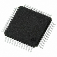
STLC7550TQF7TR STMicroelectronics, STLC7550TQF7TR Datasheet - Page 8

STLC7550TQF7TR
Manufacturer Part Number
STLC7550TQF7TR
Description
IC ANALOG FRONT END LV 48-TQFP
Manufacturer
STMicroelectronics
Datasheet
1.E-STLC7550TQF7.pdf
(24 pages)
Specifications of STLC7550TQF7TR
Number Of Bits
16
Number Of Channels
1
Power (watts)
30mW
Voltage - Supply, Analog
3V
Voltage - Supply, Digital
3V
Package / Case
48-TQFP, 48-VQFP
Lead Free Status / RoHS Status
Lead free / RoHS Compliant
Available stocks
Company
Part Number
Manufacturer
Quantity
Price
Company:
Part Number:
STLC7550TQF7TR
Manufacturer:
STMicroelectronics
Quantity:
10 000
Functional description
2
2.1
2.1.1
2.1.2
2.2
2.2.1
2.2.2
8/24
Transmit D/A section
Receive A/D section
Functional description
The functions included in the Tx D/A section are detailed hereafter. 16-bit 2’s complement
data format is used in the DAC channel.
Transmit Low Pass Filters
The transmit low pass filter is basically an interpolating filter including a sinx/x correction. It
is a combination of Finite Impulse Response filter (FIR) and an Infinite Impulse Response
filter (IIR). The digital signal from the serial interface gets interpolated by 2, 3, 4, 5 or 6 x
Sampling Frequency (FS) through the IIR filter. The signal is further interpolated by 32 x FS
x n (with n equal to 2, 3, 4, 5, 6) through the IIR and FIR filter. The low pass filter is followed
by the DAC. The DAC is oversampled at 64, 96, 128, 160, 192 x FS. The oversampling ratio
is user selectable.
D/A Converter
The oversampled D/A converter includes a second order digital noise shaper, a one bit D/A
converter and a single pole analog low-pass filter. The attenuation of the last output stage
can be programmed to 0dB, +6dB or infinite. The cut-off frequency of the single pole switch-
capacitor lowpass is:
with OCLK = Oversampling Clock frequency.
Continuous-time filtering of the analog differential output is necessary using an off-chip
amplifier and a few external passive components. At least 79dB signal to noise plus
distortion ratio can obtained in the frequency band of 0.425 x 9.6kHz (with an oversampling
ratio equal to 160).
The different functions included in the ADC channel section are described below. 16-bit 2’s
complement data format is used in the ADC.
A/D Converter
The oversampled A/D converter is based on a second order sigma-delta modulator. To
produce excellent common-mode rejection of unwanted signals, the analog signal is
processed differentially until it is converted to digital data. Single-ended mode can also be
used. The ADC is oversampled at 64, 96, 128, 160 or 192 x FS. The oversampling ratio is
user selectable. At least -85dB SNDR can be expected in the 0.425 x 9.6kHz bandwidth with
a -6dBr differential input signal and an oversampling ratio equal to 160.
Receive Low Pass Filter
It is a decimation filter. The decimation is performed by two decimation digital filters : one
decimation FIR filter and one decimation IIR filter. The purpose of the FIR filter is to
decimate 32 times the digital signal coming from the ADC modulator.
fc
Rev 9
–
3dB
=
--------------------- -
2 π 10
OCLK
⋅
⋅
STLC7550


