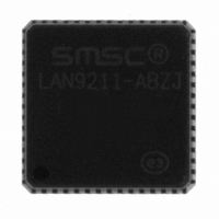
LAN9211-ABZJ SMSC, LAN9211-ABZJ Datasheet - Page 93

LAN9211-ABZJ
Manufacturer Part Number
LAN9211-ABZJ
Description
IC ETHERNET CTLR SGL CHIP 56-QFN
Manufacturer
SMSC
Type
Single Chip MAC and PHY Controllerr
Datasheet
1.LAN9211-ABZJ.pdf
(147 pages)
Specifications of LAN9211-ABZJ
Controller Type
Ethernet Controller
Interface
Serial EEPROM
Voltage - Supply
3.3V
Operating Temperature
0°C ~ 70°C
Mounting Type
Surface Mount
Package / Case
56-QFN
Product
Ethernet Controllers
Number Of Transceivers
1
Standard Supported
IEEE 802.3 or IEEE 802.3u
Data Rate
10 Mbps or 100 Mbps
Supply Voltage (max)
5 V
Supply Voltage (min)
3.3 V
Supply Current (max)
86 mA
Maximum Operating Temperature
+ 70 C
Ethernet Connection Type
100BASE-TX or 10BASE-T
Minimum Operating Temperature
0 C
Mounting Style
SMD/SMT
No. Of Ports
2
Ethernet Type
IEEE 802.3 / 802.3u
Interface Type
HBI
Supply Current
86mA
Supply Voltage Range
2.97V To 3.63V
Operating Temperature Range
0°C To +70°C
Rohs Compliant
Yes
Lead Free Status / RoHS Status
Lead free / RoHS Compliant
Current - Supply
-
Lead Free Status / Rohs Status
Lead free / RoHS Compliant
Other names
638-1049-6
Available stocks
Company
Part Number
Manufacturer
Quantity
Price
Company:
Part Number:
LAN9211-ABZJ
Manufacturer:
Standard
Quantity:
3
Part Number:
LAN9211-ABZJ
Manufacturer:
SMSC
Quantity:
20 000
High-Performance Small Form Factor Single-Chip Ethernet Controller with HP Auto-MDIX Support
Datasheet
SMSC LAN9211
BITS
5-4
3
2
1
0
WAKE-UP Status (WUPS) – This field indicates the cause of a wake-up
event detection as follows
00b -- No wake-up event detected
01b -- Energy detected
10b -- Wake-up frame or magic packet detected
11b -- Indicates multiple events occurred
WUPS bits are cleared by writing a ‘1’ to the appropriate bit. The device must
return to the D0 state (READY bit set) before these bits can be cleared.
Note:
PME indication (PME_IND). The PME signal can be configured as a pulsed
output or a static signal, which is asserted upon detection of a wake-up
event.
When set, the PME signal will pulse active for 50mS upon detection of a
wake-up event.
When clear, the PME signal is driven continuously upon detection of a wake-
up event.
The PME signal can be deactivated by clearing the WUPS bits, or by
clearing the appropriate enable (refer to
Management Event Indicators," on page
PME Polarity (PME_POL). This bit controls the polarity of the PME signal.
When set, the PME output is an active high signal. When reset, it is active
low. When PME is configured as an open-drain output this field is ignored,
and the output is always active low.
PME Enable (PME_EN). When set, this bit enables the external PME signal.
This bit does not affect the PME interrupt (PME_INT).
Device Ready (READY). When set, this bit indicates that LAN9211 is ready
to be accessed. This register can be read when LAN9211 is in any power
management mode. Upon waking from any power management mode,
including power-up, the host processor can interrogate this field as an
indication when LAN9211 has stabilized and is fully alive. Reads and writes
of any other address are invalid until this bit is set.
Note:
Note:
In order to clear this bit, it is required that all event sources be
cleared as well. The event sources are described in
PME and PME_INT Signal Generationon page
With the exception of HW_CFG and PMT_CTRL, read access to
any internal resources is forbidden while the READY bit is cleared.
On power-up, this bit can be polled to indicate when a valid soft
reset (SRST) can be performed.
DESCRIPTION
DATASHEET
Section 3.10.2.3, "Power
45).
93
45.
Figure 3.12
NASR
R/WC
TYPE
R/W
R/W
R/W
RO
Revision 2.7 (03-15-10)
DEFAULT
00
0b
0b
0b
-


