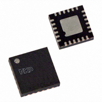
SC18IS601IBS,151 NXP Semiconductors, SC18IS601IBS,151 Datasheet - Page 17

SC18IS601IBS,151
Manufacturer Part Number
SC18IS601IBS,151
Description
IC SPI TO I2C BUS 24-HVQFN
Manufacturer
NXP Semiconductors
Datasheet
1.SC18IS600IBS151.pdf
(30 pages)
Specifications of SC18IS601IBS,151
Package / Case
24-VQFN Exposed Pad, 24-HVQFN, 24-SQFN, 24-DHVQFN
Controller Type
I²C Bus Controller
Interface
SPI
Voltage - Supply
2.4 V ~ 3.6 V
Current - Supply
11mA
Operating Temperature
-40°C ~ 85°C
Mounting Type
Surface Mount
Maximum Operating Frequency
12 MHz
Maximum Operating Temperature
+ 85 C
Minimum Operating Temperature
- 40 C
Mounting Style
SMD/SMT
Supply Voltage (max)
3.6 V
Supply Voltage (min)
2.4 V
Lead Free Status / RoHS Status
Lead free / RoHS Compliant
For Use With
568-3511 - DEMO BOARD SPI TO I2C
Lead Free Status / Rohs Status
Lead free / RoHS Compliant
Other names
568-4710
935286979151
SC18IS601IBS-S
935286979151
SC18IS601IBS-S
NXP Semiconductors
7. Limiting values
Table 10.
In accordance with the Absolute Maximum Rating System (IEC 60134).
[1]
[2]
[3]
SC18IS600_601_5
Product data sheet
Symbol
T
T
V
I
I
I
P
OH(I/O)
OL(I/O)
I/O(tot)(max)
amb(bias)
stg
n
tot
/pack
This product includes circuitry specifically designed for the protection of its internal devices from the damaging effects of excessive
static charge. Nonetheless, it is suggested that conventional precautions be taken to avoid applying greater than the rated maximum.
Parameters are valid over the operating temperature range unless otherwise specified. All voltages are with respect to V
otherwise noted.
Based on package heat transfer, not device power consumption.
Limiting values
Parameter
bias ambient temperature
storage temperature
voltage on any other pin
HIGH-level output current per input/output pin
LOW-level output current per input/output pin
maximum total I/O current
total power dissipation per package
6.6.9 Power-down mode
The SC18IS600/601 can be placed in a low-power mode where the internal oscillator is
stopped and it will no longer respond to SPI messages. Enter the Power-down mode by
sending the power-down command (0x30) followed by the two defined bytes, which are
0x5A followed by 0xA5. If the exact message is not received, the device will not enter the
power-down state.
Before entering the power-down state, WAKEUP/IO4 should be placed in a HIGH state.
To exit the power-down state, the WAKEUP/IO4 should be brought LOW. After leaving the
power-down state, the WAKEUP/IO4 can once again be used as a general-purpose IO
pin.
Fig 21. Power-down mode
SPI host sends
COMMAND
SCLK
MOSI
0x30
CS
Rev. 05 — 28 July 2008
0x5A
character 0x30
0xA5
Conditions
operating
referenced to V
[1][2]
character 0x5A
SS
[3]
SC18IS600/601
Min
-
-
-
-
55
65
0.5
character 0xA5
SPI to I
002aab725
Max
+125
+150
+5.5
8
20
120
1.5
© NXP B.V. 2008. All rights reserved.
2
C-bus interface
SS
unless
Unit
V
mA
mA
mA
W
C
C
17 of 30


