TDGL003 Microchip Technology, TDGL003 Datasheet - Page 107
TDGL003
Manufacturer Part Number
TDGL003
Description
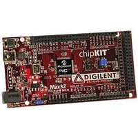
ChipKIT Max32 Development Board PIC32 Boards And Kits
Manufacturer
Microchip Technology
Series
PIC® 32MXr
Type
MCUr
Specifications of TDGL003
Silicon Manufacturer
Microchip
Core Architecture
MIPS
Core Sub-architecture
PIC32
Silicon Core Number
PIC32MX
Silicon Family Name
PIC32MX795Fxxxx
Kit Contents
Board Only
Contents
Board
Lead Free Status / Rohs Status
Lead free / RoHS Compliant
For Use With/related Products
MPLAB®, Arduino™ Mega


15.0
The Input Capture module is useful in applications
requiring frequency (period) and pulse measurement.
The PIC32MX3XX/4XX devices support up to five input
capture channels.
The Input Capture module captures the 16-bit or 32-bit
value of the selected Time Base registers when an
event occurs at the ICx pin. The events that cause a
capture event are listed below in three categories:
1.
FIGURE 15-1:
© 2011 Microchip Technology Inc.
- Capture timer value on every falling edge of
- Capture timer value on every rising edge of
Note 1: This data sheet summarizes the features
Simple Capture Event modes
input at ICx pin
input at ICx pin
2: Some registers and associated bits
INPUT CAPTURE
of the PIC32MX3XX/4XX family of
devices. It is not intended to be a
comprehensive reference source. To
complement the information in this data
sheet, refer to Section 15. “Input
Capture” (DS61122) of the “PIC32
Family Reference Manual”, which is
available from the Microchip web site
(www.microchip.com/PIC32).
described in this section may not be
available on all devices. Refer to
Section 4.0 “Memory Organization”
this data sheet for device-specific register
and bit information.
ICM<2:0>
Prescaler
1, 4, 16
ICx Input
INPUT CAPTURE BLOCK DIAGRAM
ICM<2:0>
FEDGE
Edge Detect
ICxCON
FIFO Control
ICBNE
ICI<1:0>
ICOV
in
ICTMR
C32
Generation
Interrupt
2.
3.
4.
Each input capture channel can select between one of
two 16-bit timers (Timer2 or Timer3) for the time base,
or two 16-bit timers (Timer2 and Timer3) together to
form a 32-bit timer. The selected timer can use either
an internal or external clock.
Other operational features include:
• Device wake-up from capture pin during CPU
• Interrupt on input capture event
• 4-word FIFO buffer for capture values
• Input capture can also be used to provide
Interrupt
Event
- Capture timer value on every 4th rising edge
- Capture timer value on every 16th rising
Sleep and Idle modes
- Interrupt optionally generated after 1, 2, 3 or
additional sources of external interrupts
ICxBUF<31:16>
Capture timer value on every edge (rising and
falling)
Capture timer value on every edge (rising and
falling), specified edge first.
Prescaler Capture Event modes
of input at ICx pin
edge of input at ICx pin
4 buffer locations are filled
PIC32MX3XX/4XX
Data Space Interface
Peripheral Data Bus
ICxBUF<15:0>
Timer3
0
Timer2
1
DS61143H-page 107
Related parts for TDGL003
Image
Part Number
Description
Manufacturer
Datasheet
Request
R

Part Number:
Description:
Manufacturer:
Microchip Technology Inc.
Datasheet:
Part Number:
Description:
Manufacturer:
Microchip Technology Inc.
Datasheet:
Part Number:
Description:
Manufacturer:
Microchip Technology Inc.
Datasheet:
Part Number:
Description:
Manufacturer:
Microchip Technology Inc.
Datasheet:
Part Number:
Description:
Manufacturer:
Microchip Technology Inc.
Datasheet:
Part Number:
Description:
Manufacturer:
Microchip Technology Inc.
Datasheet:
Part Number:
Description:
Manufacturer:
Microchip Technology Inc.
Datasheet:
Part Number:
Description:
Manufacturer:
Microchip Technology Inc.
Datasheet: