TDGL003 Microchip Technology, TDGL003 Datasheet - Page 151
TDGL003
Manufacturer Part Number
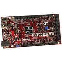
TDGL003
Description
ChipKIT Max32 Development Board PIC32 Boards And Kits
Manufacturer
Microchip Technology
Series
PIC® 32MXr
Type
MCUr
Specifications of TDGL003
Silicon Manufacturer
Microchip
Core Architecture
MIPS
Core Sub-architecture
PIC32
Silicon Core Number
PIC32MX
Silicon Family Name
PIC32MX795Fxxxx
Kit Contents
Board Only
Contents
Board
Lead Free Status / Rohs Status
Lead free / RoHS Compliant
For Use With/related Products
MPLAB®, Arduino™ Mega


29.0
This section provides an overview of PIC32MX3XX/4XX electrical characteristics. Additional information will be provided
in future revisions of this document as it becomes available.
Absolute maximum ratings for the PIC32MX3XX/4XX are listed below. Exposure to these maximum rating conditions
for extended periods may affect device reliability. Functional operation of the device at these or any other conditions
above the parameters indicated in the operation listings of this specification is not implied.
Absolute Maximum Ratings
(Note 1)
Ambient temperature under bias.............................................................................................................-40°C to +105°C
Storage temperature .............................................................................................................................. -65°C to +150°C
Voltage on V
Voltage on any pin that is not 5V tolerant, with respect to V
Voltage on any 5V tolerant pin with respect to V
Voltage on any 5V tolerant pin with respect to V
Voltage on V
Voltage on V
Maximum current out of V
Maximum current into V
Maximum output current sunk by any I/O pin..........................................................................................................25 mA
Maximum output current sourced by any I/O pin ....................................................................................................25 mA
Maximum current sunk by all ports .......................................................................................................................200 mA
Maximum current sourced by all ports (Note 2)....................................................................................................200 mA
© 2011 Microchip Technology Inc.
Note 1: Stresses above those listed under “Absolute Maximum Ratings” may cause permanent damage to the
2: Maximum allowable current is a function of device maximum power dissipation (see
3: See the
ELECTRICAL CHARACTERISTICS
device. This is a stress rating only and functional operation of the device at those or any other conditions
above those indicated in the operation listings of this specification is not implied. Exposure to maximum
rating conditions for extended periods may affect device reliability.
DD
CORE
BUS
with respect to V
with respect to V
with respect to V
“Pin
DD
SS
Diagrams” section for the 5V tolerant pins.
pin(s) (Note 2)............................................................................................................300 mA
pin(s) .......................................................................................................................300 mA
SS
SS
SS
......................................................................................................... -0.3V to +4.0V
....................................................................................................... -0.3V to +5.5V
....................................................................................................... -0.3V to 2.0V
SS
SS
when V
when V
DD
DD
SS
≥ 2.3V (Note 3)........................................ -0.3V to +5.5V
< 2.3V (Note 3)........................................ -0.3V to +3.6V
(Note 3)......................................... -0.3V to (V
PIC32MX3XX/4XX
Table
DS61143H-page 151
29-2).
DD
+ 0.3V)
Related parts for TDGL003
Image
Part Number
Description
Manufacturer
Datasheet
Request
R

Part Number:
Description:
Manufacturer:
Microchip Technology Inc.
Datasheet:
Part Number:
Description:
Manufacturer:
Microchip Technology Inc.
Datasheet:
Part Number:
Description:
Manufacturer:
Microchip Technology Inc.
Datasheet:
Part Number:
Description:
Manufacturer:
Microchip Technology Inc.
Datasheet:
Part Number:
Description:
Manufacturer:
Microchip Technology Inc.
Datasheet:
Part Number:
Description:
Manufacturer:
Microchip Technology Inc.
Datasheet:
Part Number:
Description:
Manufacturer:
Microchip Technology Inc.
Datasheet:
Part Number:
Description:
Manufacturer:
Microchip Technology Inc.
Datasheet: