TDGL003 Microchip Technology, TDGL003 Datasheet - Page 32
TDGL003
Manufacturer Part Number
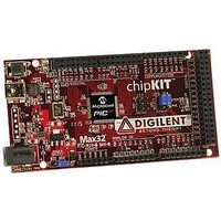
TDGL003
Description
ChipKIT Max32 Development Board PIC32 Boards And Kits
Manufacturer
Microchip Technology
Series
PIC® 32MXr
Type
MCUr
Specifications of TDGL003
Silicon Manufacturer
Microchip
Core Architecture
MIPS
Core Sub-architecture
PIC32
Silicon Core Number
PIC32MX
Silicon Family Name
PIC32MX795Fxxxx
Kit Contents
Board Only
Contents
Board
Lead Free Status / Rohs Status
Lead free / RoHS Compliant
For Use With/related Products
MPLAB®, Arduino™ Mega


PIC32MX3XX/4XX
FIGURE 2-1:
2.2.1
The use of a bulk capacitor is recommended to improve
power supply stability. Typical values range from 4.7 µF
to 47 µF. This capacitor should be located as close to
the device as possible.
2.3
2.3.1
A low-ESR (< 1 Ohm) capacitor is required on the
V
voltage regulator output. The V
be connected to V
with at least a 6V rating, connected to ground. The type
can be ceramic or tantalum. Refer to
“Electrical Characteristics”
on C
connecting the ENVREG pin to V
2.3.2
In this mode the core voltage is supplied externally
through the V
10 µF is recommended on the V
mode is enabled by grounding the ENVREG pin.
The placement of this capacitor should be close to the
V
not exceed one-quarter inch (6 mm). Refer to
Section 26.3 “On-Chip Voltage Regulator”
details.
DS61143H-page 32
CAP
CAP
0.1 µF
Ceramic
C
V
BP
DD
R
/V
/V
EFC
C
CORE
CORE
R1
Capacitor on Internal Voltage
Regulator (V
specifications. This mode is enabled by
BULK CAPACITORS
INTERNAL REGULATOR MODE
EXTERNAL REGULATOR MODE
. It is recommended that the trace length
10Ω
pin, which is used to stabilize the internal
MCLR
V
V
CORE
SS
DD
DD
/V
, and must have a C
CAP
RECOMMENDED
MINIMUM CONNECTION
PIC32MX
C
CAP
pin. A low-ESR capacitor of
EFC
0.1 µF
Ceramic
C
BP
for additional information
/V
CAP
CORE
DD
CAP
/V
.
CORE
/V
)
CORE
V
V
EFC
DD
Section 29.0
SS
0.1 µF
Ceramic
C
0.1 µF
Ceramic
C
pin must not
BP
BP
capacitor,
0.1 µF
Ceramic
C
pin. This
BP
for
2.4
The MCLR pin provides for two specific device
functions:
• Device Reset
• Device Programming and Debugging
Pulling The MCLR pin low generates a device reset.
Figure 2-2
device programming and debugging, the resistance
and capacitance that can be added to the pin must
be considered. Device programmers and debuggers
drive the MCLR pin. Consequently, specific voltage
levels (V
not be adversely affected. Therefore, specific values
of R and C will need to be adjusted based on the
application and PCB requirements.
For example, as illustrated in
recommended that the capacitor C, be isolated from
the MCLR pin during programming and debugging
operations.
Place the components shown in
one-quarter inch (6 mm) from the MCLR pin.
FIGURE 2-2:
Note 1: R ≤ 10 kΩ is recommended. A suggested start-
2: R1 ≤ 470Ω will limit any current flowing into
3: The capacitor can be sized to prevent uninten-
Master Clear (MCLR) Pin
IH
illustrates a typical MCLR circuit. During
ing value is 10 kΩ. Ensure that the MCLR pin
V
MCLR from the external capacitor C, in the
event of MCLR pin breakdown, due to
Electrostatic Discharge (ESD) or Electrical
Overstress (EOS). Ensure that the MCLR pin
V
tional resets from brief glitches or to extend the
device reset period during POR.
and V
V
IH
IH
DD
R
and V
and V
JP
C
IL
) and fast signal transitions must
IL
IL
specifications are met.
specifications are met.
EXAMPLE OF MCLR PIN
CONNECTIONS
R1
© 2011 Microchip Technology Inc.
MCLR
PIC32MX
Figure
Figure 2-2
2-2, it is
within
Related parts for TDGL003
Image
Part Number
Description
Manufacturer
Datasheet
Request
R

Part Number:
Description:
Manufacturer:
Microchip Technology Inc.
Datasheet:
Part Number:
Description:
Manufacturer:
Microchip Technology Inc.
Datasheet:
Part Number:
Description:
Manufacturer:
Microchip Technology Inc.
Datasheet:
Part Number:
Description:
Manufacturer:
Microchip Technology Inc.
Datasheet:
Part Number:
Description:
Manufacturer:
Microchip Technology Inc.
Datasheet:
Part Number:
Description:
Manufacturer:
Microchip Technology Inc.
Datasheet:
Part Number:
Description:
Manufacturer:
Microchip Technology Inc.
Datasheet:
Part Number:
Description:
Manufacturer:
Microchip Technology Inc.
Datasheet: