TDGL003 Microchip Technology, TDGL003 Datasheet - Page 29
TDGL003
Manufacturer Part Number
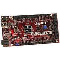
TDGL003
Description
ChipKIT Max32 Development Board PIC32 Boards And Kits
Manufacturer
Microchip Technology
Series
PIC® 32MXr
Type
MCUr
Specifications of TDGL003
Silicon Manufacturer
Microchip
Core Architecture
MIPS
Core Sub-architecture
PIC32
Silicon Core Number
PIC32MX
Silicon Family Name
PIC32MX795Fxxxx
Kit Contents
Board Only
Contents
Board
Lead Free Status / Rohs Status
Lead free / RoHS Compliant
For Use With/related Products
MPLAB®, Arduino™ Mega


TABLE 1-1:
© 2011 Microchip Technology Inc.
PGED2
PGEC2
MCLR
AV
AV
V
V
V
Vss
V
V
Legend: CMOS = CMOS compatible input or output
Note 1:
Pin Name
DD
CORE
CAP
REF
REF
DD
SS
+
-
/
ST = Schmitt Trigger input with CMOS levels
TTL = TTL input buffer
Pin numbers are provided for reference only. See the
QFN/TQFP
10, 26, 38 2, 16, 37,
9, 25, 41
64-pin
18
17
19
20
56
16
15
7
PINOUT I/O DESCRIPTIONS (CONTINUED)
Pin Number
100-pin
15, 36,
45, 65,
46, 62
TQFP
27
26
13
30
31
85
75
29
28
(1)
A8, B10,
E7, F10,
121-pin
C2, C9,
G5, H4,
D4, D5,
E5, F8,
F5, G6,
G7, H3
H6, K8
XBGA
B7
K3
J3
L1
F1
J4
L3
L2
Type
Pin
I/O
I/P
P
P
P
P
P
I
I
I
Analog
Analog
Buffer
Type
ST
ST
ST
—
—
—
P
P
Analog = Analog input
O = Output
“Pin
Data I/O pin for programming/debugging
communication channel 2.
Clock input pin for programming/debugging
communication channel 2.
Master Clear (Reset) input. This pin is an active-low
Reset to the device.
Positive supply for analog modules. This pin must be
connected at all times.
Ground reference for analog modules.
Positive supply for peripheral logic and I/O pins.
Capacitor for Internal Voltage Regulator.
Ground reference for logic and I/O pins.
Analog voltage reference (high) input.
Analog voltage reference (low) input.
Diagrams” section for device pin availability.
PIC32MX3XX/4XX
Description
P = Power
I = Input
DS61143H-page 29
Related parts for TDGL003
Image
Part Number
Description
Manufacturer
Datasheet
Request
R

Part Number:
Description:
Manufacturer:
Microchip Technology Inc.
Datasheet:
Part Number:
Description:
Manufacturer:
Microchip Technology Inc.
Datasheet:
Part Number:
Description:
Manufacturer:
Microchip Technology Inc.
Datasheet:
Part Number:
Description:
Manufacturer:
Microchip Technology Inc.
Datasheet:
Part Number:
Description:
Manufacturer:
Microchip Technology Inc.
Datasheet:
Part Number:
Description:
Manufacturer:
Microchip Technology Inc.
Datasheet:
Part Number:
Description:
Manufacturer:
Microchip Technology Inc.
Datasheet:
Part Number:
Description:
Manufacturer:
Microchip Technology Inc.
Datasheet: