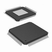
HMP8117CNZ Intersil, HMP8117CNZ Datasheet - Page 16

HMP8117CNZ
Manufacturer Part Number
HMP8117CNZ
Description
IC VIDEO DECODER NTSC/PAL 80PQFP
Manufacturer
Intersil
Type
Video Decoderr
Datasheet
1.HMP8117CNZ.pdf
(45 pages)
Specifications of HMP8117CNZ
Applications
Video
Voltage - Supply, Analog
4.75 V ~ 5.25 V
Voltage - Supply, Digital
4.75 V ~ 5.25 V
Mounting Type
Surface Mount
Package / Case
80-MQFP, 80-PQFP
Lead Free Status / RoHS Status
Lead free / RoHS Compliant
Available stocks
Company
Part Number
Manufacturer
Quantity
Price
CAPTIONING DISABLED ON BOTH LINES
In this case, any caption data present is ignored.
The Caption odd field Read status bit and the Caption even
field Read status bit are always a “0”.
ODD FIELD CAPTIONING
In this case, any caption data present on line 284 (or line 281
or 335 in the PAL modes) is ignored. Caption data present
on line 21 (or line 18 or 22 in the PAL modes) is captured
into a shift register then transferred to CLOSED
CAPTION_ODD_A register 20
CAPTION_ODD_B register 21
The Caption even field Read status bit is always a “0”. The
Caption odd field Read status bit is set to “1” after data has
been transferred from the shift register to the CLOSED
CAPTION_ODD_A and CLOSED CAPTION_ODD_B
registers. It is set to “0” after the data has been read out.
EVEN FIELD CAPTIONING
In this case, any caption data present on line 21 (or line 18 or
22 in the PAL modes) is ignored. Caption data present on
line 284 (or line 281 or 335 in the PAL modes) is captured
into a shift register then transferred to CLOSED
CAPTION_EVEN_A register 22
CAPTION_EVEN_B register 23
The Caption odd field Read status bit is always a “0”. The
Caption even field Read status bit is set to “1” after data has
been transferred from the shift register to the CLOSED
CAPTION_EVEN_A and CLOSED CAPTION_EVEN_B
registers. It is set to “0” after the data has been read out.
ODD AND EVEN FIELD CAPTIONING
Caption data present on line 21 (or line 18 or 22 in the PAL
modes) is captured into a shift register then transferred to
the CLOSED CAPTION_ODD_A and CLOSED
CAPTION_ODD_B registers. Caption data present on line
284 (or line 281 or 335 in the PAL modes) is captured into a
shift register then transferred to the CLOSED
CAPTION_EVEN_A and CLOSED CAPTION_EVEN_B
registers.
The Caption odd field Read status bit is set to “1” after data
has been transferred from the shift register to the CLOSED
CAPTION_ODD_A and CLOSED CAPTION_ODD_B
registers. It is set to “0” after the data has been read out.
The Caption even field Read status bit is set to “1” after data
has been transferred from the shift register to the CLOSED
CAPTION_EVEN_A and CLOSED CAPTION_EVEN_B
registers. It is set to “0” after the data has been read out.
Widescreen Signalling (WSS)
During WSS capture (ITU-R BT.1119 and EIAJ CPX-1204),
the scan lines containing WSS information are monitored. If
WSS is enabled and WSS data is present, the WSS data is
loaded into the WSS data registers.
16
H
H
H
H
.
and CLOSED
.
and CLOSED
HMP8117
DETECTION OF WSS
The WSS decoder monitors the appropriate scan lines
looking for the run-in and start codes used by WSS. If found,
it locks to the run-in code, the WSS data is sampled and
loaded into shift registers, and the data is then transferred to
the WSS data registers.
If the run-in and start codes are not found, it is assumed the
scan line contains video data unless other VBI information is
detected, such as teletext.
Once the run-in and start codes are found on the appropriate
scan line for four consecutive odd fields, the WSS Line 20
Detect status bit is set to “1”. It is reset to “0” when the run-in
and start codes are not found on the appropriate scan lines
for four consecutive odd fields.
Once the run-in and start codes are found on the appropriate
scan line for four consecutive even fields, the WSS Line 283
Detect status bit is set to “1”. It is reset to “0” when the clock
run-in and start bits are not found on the appropriate scan
lines for four consecutive even fields.
READING THE WSS DATA
The WSS data registers may be accessed in two ways: via
the I
WSS DISABLED ON BOTH LINES
In this case, any WSS data present is ignored.
The WSS odd field Read status bit and the WSS even field
Read status bit are always a “0”.
ODD FIELD WSS
In this case, any WSS data present on line 283 (or line 280
or 336 in the PAL modes) is ignored. WSS data present on
line 20 (or line 17 or 23 in the PAL modes) is captured into a
shift register then transferred to the WSS_ODD_A and
WSS_ODD_B data registers.
The WSS even field Read status bit is always a “0”. The
WSS odd field Read status bit is set to “1” after data has
been transferred from the shift register to the WSS_ODD_A
and WSS_ODD_B registers. It is set to “0” after the data has
been read out.
EVEN FIELD WSS
In this case, any WSS data present on line 20 (or line 17 or
23 in the PAL modes) is ignored. WSS data present on line
283 (or line 280 or 336 in the PAL modes) is captured into a
shift register then transferred to the WSS_EVEN_A and
WSS_EVEN_B data registers.
The WSS odd field Read status bit is always a “0”. The WSS
even field Read status bit is set to “1” after data has been
transferred from the shift register to the WSS_EVEN_A and
WSS_EVEN_B registers. It is set to “0” after the data has
been read out.
2
C interface or as BT.656 ancillary data.
April 19, 2007
FN4643.3


