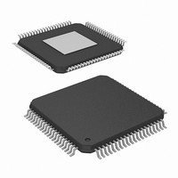
HMP8117CNZ Intersil, HMP8117CNZ Datasheet - Page 28

HMP8117CNZ
Manufacturer Part Number
HMP8117CNZ
Description
IC VIDEO DECODER NTSC/PAL 80PQFP
Manufacturer
Intersil
Type
Video Decoderr
Datasheet
1.HMP8117CNZ.pdf
(45 pages)
Specifications of HMP8117CNZ
Applications
Video
Voltage - Supply, Analog
4.75 V ~ 5.25 V
Voltage - Supply, Digital
4.75 V ~ 5.25 V
Mounting Type
Surface Mount
Package / Case
80-MQFP, 80-PQFP
Lead Free Status / RoHS Status
Lead free / RoHS Compliant
Available stocks
Company
Part Number
Manufacturer
Quantity
Price
NO.
NO.
BIT
BIT
3-1
7
6
5
4
0
7
6
5
4
3
2
1
0
Vertical Lock
Status
Horizontal Lock
Status
Color Lock
Status
Input Video
Detect Status
MV Detection Status These bits are read-only. Data written to this bit is ignored.
Auto Detect
Video Standard
Status
Genlock Loss
Interrupt Mask
Input Signal Loss
Interrupt Mask
Closed Caption
Interrupt Mask
WSS
Interrupt Mask
Teletext
Interrupt Mask
MV Interrupt Mask
Auto Detect
Video Standard
Interrupt Mask
Vertical Sync
Interrupt Mask
FUNCTION
FUNCTION
28
This bit is read-only. Data written to this bit is ignored.
If set to “1”, the decoder is vertically locked to the input signal.
This bit is read-only. Data written to this bit is ignored.
If set to “1”, the decoder is horizontally locked to the input signal.
This bit is read-only. Data written to this bit is ignored.
If set to “1”, the decoder is chroma locked to the input signal.
This bit is read-only. Data written to this bit is ignored.
If set to “1”, video is detected on the input signal.
000
001
010
011
100
101
110
111
This bit is read-only. Data written to this bit is ignored.
If set to “1”, the decoder determined the video standard on the input signal.
This bit is enabled by the Input Format Register 01
If set to “1”, an interrupt is enabled for the loss of genlock.
If set to “1”, an interrupt is enabled for the loss of input video signal.
If set to “1”, an interrupt is enabled for new data in the closed caption data registers.
If set to “1”, an interrupt is enabled for new data in the WSS data registers.
If set to “1”, an interrupt is enabled for the detection of teletext data in the current field.
If set to “1”, an interrupt is enabled for a change in the MV Detection Status Register 0E
If set to “1”, an interrupt is enabled for the successful auto detection of a video standard.
If set to “1”, an interrupt is enabled for the start of a new field.
B
B
B
B
B
B
B
B
= No PSP present, 4-line Stripes (invalid MV scheme, may indicate false detection)
= PSP present, 4-line Stripes
= No PSP present, 2-line Stripes (invalid MV scheme, may indicate false detection)
= No MV present
= PSP present, No Stripes
= PSP present, 2-Line Stripes
= reserved
= reserved
TABLE 23. INTERRUPT MASK REGISTER
TABLE 22. VIDEO STATUS REGISTER
SUB ADDRESS = 0E
SUB ADDRESS = 0F
HMP8117
DESCRIPTION
DESCRIPTION
H
H
H
bit 4.
H
.
April 19, 2007
RESET
RESET
STATE
STATE
000
0
0
0
0
0
0
0
0
0
0
0
0
0
FN4643.3
B
B
B
B
B
B
B
B
B
B
B
B
B
B


