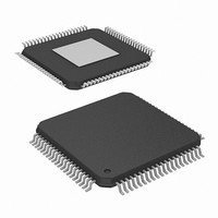
HMP8117CNZ Intersil, HMP8117CNZ Datasheet - Page 25

HMP8117CNZ
Manufacturer Part Number
HMP8117CNZ
Description
IC VIDEO DECODER NTSC/PAL 80PQFP
Manufacturer
Intersil
Type
Video Decoderr
Datasheet
1.HMP8117CNZ.pdf
(45 pages)
Specifications of HMP8117CNZ
Applications
Video
Voltage - Supply, Analog
4.75 V ~ 5.25 V
Voltage - Supply, Digital
4.75 V ~ 5.25 V
Mounting Type
Surface Mount
Package / Case
80-MQFP, 80-PQFP
Lead Free Status / RoHS Status
Lead free / RoHS Compliant
Available stocks
Company
Part Number
Manufacturer
Quantity
Price
NO.
NO.
BIT
BIT
7-6
5-4
2-0
7-6
5-4
3-2
3
1
0
Lock Loss
Video Gain
Select
Video Gain
Control Select
Digital Anti-Alias
Filter Control
Video Signal
Input Select
Digital Color Gain
Control Select
Color Killer
Select
Color Coring
Select
Contrast Control
Select
Color Low-Pass
Filter Select
FUNCTION
FUNCTION
25
If bits 5-4 do not equal “01”, these bits indicate what mode the AGC circuitry will be after loss of
sync. If bits 5-4 equal “01”, these bits are ignored.
00 = Automatic gain control: bits 5-4 will be reset to “01”
01 = Maintain fixed gain: bits 5-4 will not be changed
10 = Normal AGC switching to fixed gain after lock achieved: bits 5-4 will not be reset to “01”
unless they indicated “freeze automatic gain control”
11 = reserved
00 = Fixed 1x gain
01 = Automatic gain control
10 = Fixed gain control. (Use gain factor from Video Gain Adjust register 1D
11 = Freeze automatic gain control
0 = Internal digital anti-alias filter is active.
1 = Internal digital anti- alias filter is bypassed. (Not Recommended)
000 = CVBS1
001 = CVBS2
010 = CVBS3
011 = S-video
1XX = reserved
00 = No gain control (gain = 1x)
01 = Automatic gain control
10 = Fixed gain control. (Use gain factor from Color Gain Adjust register 1C
11 = Freeze automatic gain control
00 = Force color on
01 = Enable color killer
10 = reserved
11 = Force color off
Coring may be used to reduce low-level noise in the CbCr signals.
00 = No coring
01 = 1 code coring
10 = 2 code coring
11 = 3 code coring
This bit specifies whether the contrast control affects just the Y data (“0”) or both the Y and CbCr
data (“1”). To avoid color shifts when changing contrast, this bit should be a “1”.
0 = Contrast controls only Y data
1 = Contrast controls Y and CbCr data
This bit selects the bandwidth of the CbCr data.
0 = 850kHz
1 = 1.5MHz
TABLE 16. ANALOG INPUT CONTROL REGISTER
TABLE 17. COLOR PROCESSING REGISTER
SUB ADDRESS = 05
SUB ADDRESS = 06
HMP8117
DESCRIPTION
DESCRIPTION
H
H
H
H
.)
.)
April 19, 2007
RESET
RESET
STATE
STATE
000
00
01
01
01
00
0
1
0
FN4643.3
B
B
B
B
B
B
B
B
B


