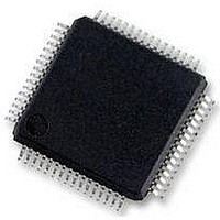
STM32F405RGT6 STMicroelectronics, STM32F405RGT6 Datasheet - Page 66

STM32F405RGT6
Manufacturer Part Number
STM32F405RGT6
Description
Microcontrollers (MCU) ARM M4 1024 FLASH 168 Mhz 192kB SRAM
Manufacturer
STMicroelectronics
Datasheet
1.STM32F407ZGT6.pdf
(167 pages)
Specifications of STM32F405RGT6
Core
ARM Cortex M4
Processor Series
STM32F4
Data Bus Width
32 bit
Maximum Clock Frequency
168 MHz
Program Memory Size
1024 KB
Data Ram Size
192 KB
On-chip Adc
Yes
Number Of Programmable I/os
51
Number Of Timers
10
Operating Supply Voltage
1.7 V to 3.6 V
Package / Case
LQFP-64
Mounting Style
SMD/SMT
A/d Bit Size
12 bit
A/d Channels Available
16
Interface Type
CAN, I2C, I2S, SPI, UART
Program Memory Type
Flash
Lead Free Status / Rohs Status
Details
Available stocks
Company
Part Number
Manufacturer
Quantity
Price
Company:
Part Number:
STM32F405RGT6
Manufacturer:
ON
Quantity:
1 001
Company:
Part Number:
STM32F405RGT6
Manufacturer:
STMicroelectronics
Quantity:
10 000
Part Number:
STM32F405RGT6
Manufacturer:
ST
Quantity:
20 000
Electrical characteristics
Table 11.
1. The average expected gain in power consumption when VOS = 0 compared to VOS = 1 is around 10% for the whole
2. If an inverted reset signal is applied to PDR_ON, this value can be lowered to 1.7 V when the device operates in a reduced
3. When the ADC is used, refer to
4. If V
5. It is recommended to power V
6. If T
7. In low power dissipation state, T
66/167
Symbol
temperature range, when the system clock frequency is between 30 and 144 MHz.
temperature range (0 to 70 °C).
V
V
V
DDA
CAP1
CAP2
P
T
T
A
REF+
A
D
J
is lower, higher P
can be tolerated during power-up and power-down operation.
pin is present, it must respect the following condition: V
General operating conditions (continued)
When the internal regulator is ON,
V
connect a stabilization capacitor.
When the internal regulator is OFF
(BYPASS_REG connected to V
V
from 1.2 V.
Power dissipation at T
suffix 6 or T
Ambient temperature for 6 suffix
version
Ambient temperature for 7 suffix
version
Junction temperature range
CAP_1
CAP_1
and V
and V
D
values are allowed as long as T
A
Parameter
= 105 °C for suffix 7
CAP_2
CAP_2
DD
Table 65: ADC
A
and V
can be extended to this range as long as T
must be supplied
pins are used to
A
= 85 °C for
DDA
from the same source. A maximum difference of 300 mV between V
characteristics.
DD
Doc ID 022152 Rev 2
(6)
),
J
LQFP64
LQFP100
LQFP144
LQFP176
UFBGA176
Maximum power dissipation
Low power dissipation
Maximum power dissipation
Low power dissipation
6 suffix version
7 suffix version
does not exceed T
DDA
-V
REF+
Conditions
< 1.2 V.
Jmax
J
does not exceed T
.
(7)
(7)
STM32F405xx, STM32F407xx
Jmax
Min
–40
–40
–40
–40
–40
–40
1.1
.
-
-
-
-
-
Max
435
465
500
526
513
105
105
125
105
125
1.3
85
DD
and
Unit
mW
°C
°C
°C
V


