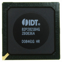
IDT82P2821BHG IDT, Integrated Device Technology Inc, IDT82P2821BHG Datasheet - Page 89

IDT82P2821BHG
Manufacturer Part Number
IDT82P2821BHG
Description
IC LINE INTERFACE UNIT 640-PBGA
Manufacturer
IDT, Integrated Device Technology Inc
Datasheet
1.IDT82P2821BHG.pdf
(151 pages)
Specifications of IDT82P2821BHG
Function
Line Interface Unit (LIU)
Interface
E1, J1, T1
Number Of Circuits
1
Voltage - Supply
1.8V, 3.3V
Operating Temperature
-40°C ~ 85°C
Mounting Type
Surface Mount
Package / Case
*
Includes
Defect and Alarm Detection, Driver Over-Current Detection and Protection, LLOS Detection, PRBSARB / IB Detection and Generation
Number Of Transceivers
1
Screening Level
Industrial
Mounting
Surface Mount
Operating Temperature (min)
-40C
Operating Temperature (max)
85C
Lead Free Status / RoHS Status
Lead free / RoHS Compliant
Current - Supply
-
Power (watts)
-
Lead Free Status / RoHS Status
Compliant, Lead free / RoHS Compliant
Other names
800-1703
82P2821BHG
82P2821BHG
Available stocks
Company
Part Number
Manufacturer
Quantity
Price
Company:
Part Number:
IDT82P2821BHG
Manufacturer:
IDT
Quantity:
170
Company:
Part Number:
IDT82P2821BHG
Manufacturer:
IDT, Integrated Device Technology Inc
Quantity:
10 000
TCF0 - Transmit Configuration Register 0
Address: 004H, 044H, 084H, 0C4H, 104H, 144H, 184H, 1C4H, (CH1~CH8)
Type: Read / Write
Default Value: 00H
Programming Information
IDT82P2821
2 - 0
Bit
7
6
5
4
3
204H, 244H, 284H, 2C4H, 304H, 344H, 384H, 3C4H, (CH9~CH16)
404H, 444H, 484H, 4C4H, 504H, (CH17~CH21)
7C4H (CH0)
7
-
T_TERM[2:0]
THZ_OC
T_SING
T_OFF
Name
OE
-
OE
6
Reserved.
This bit determines the output of the Line Driver, i.e., the output on the TTIPn and TRINGn pins.
0: High-Z. (default)
1: Normal operation.
This bit determines whether the transmitter is powered down.
0: Normal operation. (default)
1: Power down.
This bit determines the output of the Line Driver, i.e., the output on the TTIPn and TRINGn pins when TOC is detected.
0: The output current is limited to 100 mAp-p. (default)
1: The output current is limited to 100 mAp-p within the first 1 ms after the TOC is detected and then the output is in High-Z state
when the TOC is detected for more than 1 ms.
This bit determines the transmit line interface.
0: Transmit Differential line interface. Both TTIPn and TRINGn are used to transmit signal to the line side. (default)
1: Transmit Single Ended line interface. Only TTIPn is used to transmit signal. TRINGn should be left open.
These bits select the impedance matching mode of the transmit path to match the cable impedance.
000: The 100 Ω internal impedance matching is selected for T1 100 Ω twisted pair cable (with transformer). (default)
001: The 110 Ω internal impedance matching is selected for J1 110 Ω twisted pair cable (with transformer).
010: The 120 Ω internal impedance matching is selected for E1 120 Ω twisted pair cable (with transformer).
011: The 75 Ω internal impedance matching is selected for E1 75 Ω coaxial cable (with transformer).
100: The 100 Ω internal impedance matching is selected for T1 100 Ω twisted pair cable (transformer-less).
101: The 110 Ω internal impedance matching is selected for J1 110 Ω twisted pair cable (transformer-less).
110: The 120 Ω internal impedance matching is selected for E1 120 Ω twisted pair cable (transformer-less).
111: The external impedance matching is selected for E1 120 Ω twisted pair cable or E1 75 Ω coaxial cable (with transformer).
T_OFF
5
THZ_OC
4
21(+1) CHANNEL HIGH-DENSITY T1/E1/J1 LINE INTERFACE UNIT
89
T_SING
3
Description
T_TERM2
2
T_TERM1
1
February 6, 2009
T_TERM0
0


