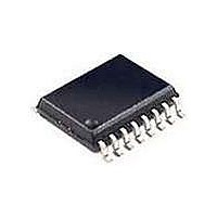
SI3050-KT Silicon Laboratories Inc, SI3050-KT Datasheet - Page 25

SI3050-KT
Manufacturer Part Number
SI3050-KT
Description
IC VOICE DAA GCI/PCM/SPI 20TSSOP
Manufacturer
Silicon Laboratories Inc
Type
Chipsetr
Specifications of SI3050-KT
Package / Case
20-TSSOP
Function
Data Access Arrangement (DAA)
Interface
PCM, Serial, SPI
Number Of Circuits
1
Voltage - Supply
3 V ~ 3.6 V
Current - Supply
8.5mA
Operating Temperature
0°C ~ 70°C
Mounting Type
Surface Mount
Includes
Line Voltage Monitor, Loop Current Monitor, Overload Detection, Parallel Handset Detection, Polarity Reversal Detection, TIP and
Product
Modem Chip
Supply Voltage (min)
3 V
Supply Current
8.5 mA
Maximum Operating Temperature
+ 70 C
Minimum Operating Temperature
0 C
Mounting Style
SMD/SMT
Lead Free Status / RoHS Status
Contains lead / RoHS non-compliant
Power (watts)
-
Lead Free Status / RoHS Status
Lead free / RoHS Compliant, Contains lead / RoHS non-compliant
Available stocks
Company
Part Number
Manufacturer
Quantity
Price
Part Number:
SI3050-KT
Manufacturer:
SILICONIX
Quantity:
20 000
Company:
Part Number:
SI3050-KTR
Manufacturer:
NEC
Quantity:
947
Part Number:
SI3050-KTR
Manufacturer:
SILICON LABS/芯科
Quantity:
20 000
affects the signal swing of the transmit signal. Silicon
Laboratories recommends that the transmit signal be
12 dB lower than normal transmit levels. A lower level
eliminates clipping from the dc offset that results from
disabling the hybrid. It is assumed in this test that the
line ac impedance is nominally 600 Ω.
Note: All test modes are mutually exclusive. If more than one
Exception Handling
The Si3050 can determine if an error occurs during
operation. Through the secondary frames of the serial
link, the controlling DSP can read several status bits.
The bit of highest importance is the frame detect bit
(FDT, Register 12, bit 6) which indicates that the
system-side (Si3050) and line-side (Si3018 or Si3019)
devices are communicating. During normal operation,
the FDT bit can be checked before reading the bits that
indicate information about the line side. If FDT is not
set, the following bits related to the line side are
invalid—RDT, RDTN, RDTP, LCS[4:0], LSID[1:0],
REVB[3:0], LVS[7:0], LCS2[7:0], ROV, BTD, DOD, and
OVL; the RGDT operation is also non-functional.
Following powerup and reset, the FDT bit is not set
because the PDL bit (Register 6 bit 4) defaults to 1. In
this state, the ISOcap is not operating and no
information about the line side can be determined. The
user must provide a valid PCLK and FSYNC to the
system and clear the PDL bit to activate the ISOcap
link. Communication with the line-side device takes less
than 10 ms to establish.
The FDT bit also can indicate if the line side executes
an off-hook request successfully. If the line side is not
connected to a phone line, the FDT bit remains cleared.
The controlling DSP must provide sufficient time for the
line side to execute the off-hook request. The maximum
time for FDT to be valid following an off-hook request is
10 ms. If the FDT bit is high, the LCS[4:0] bits indicate
the amount of loop current flowing. If the FDT is not set
following an off-hook request, the PDL bit (Register 6,
bit 4) must be set high for at least 1 ms to reset the line
side.
Revision Identification
The Si3050 provides information to determine the
revision of the Si3050 and/or the Si3018/19. The
REVA[3:0] bits (Register 11) identify the revision of the
Si3050. The REVB[3:0] bits (Register 13) identify the
revision of the line-side device. Table 14 lists revision
values and might contain future revisions not yet in
existence.
test mode is enabled concurrently, the results are
unpredictable.
Rev. 1.0
Transmit/Receive Full Scale Level
(Si3019 Line-Side Only)
The Si3050 supports a higher maximum transmit and
receive level mode (full scale). The full scale TX/RX
level
(Register 31, bit 7). With FULL = 1, the full scale signal
level increases to support voice applications that require
higher signal levels. With the full bit set, the DAA can
transmit and receive +3.2 dBm into a 600 Ω load (or
1 dBV into all reference impedances). The default full
scale value is 0 dBm (FULL = 0).
Parallel Handset Detection
The Si3050 can detect a parallel handset going
off-hook. When the Si3050 is off-hook, the loop current
can be monitored with the LCS or LCS2 bits. A
significant drop in loop current signals a parallel handset
going off-hook. If a parallel handset going off-hook
causes the loop current to drop to 0, the LCS and LCS2
bits will read all 0s. Additionally, the Drop-Out Detect
(DOD) bit will fire (and generate an interrupt if the
DODM bit is set) indicating that the line-derived power
supply has collapsed.
With the Si3019 line side, the LVS bits also can be read
when on- or off-hook to determine the line voltage.
Significant drops in line voltage can signal a parallel
handset. For the Si3050 to operate in parallel with
another handset, the parallel handset must have a
sufficiently high dc termination to support two off-hook
DAAs on the same line. Improved parallel handset
operation can be achieved by changing the dc
impedance from 50 Ω to 800 Ω and reducing the DCT
pin voltage with the DCV[1:0] bits.
Line Voltage/Loop Current Sensing
The Si3050 can measure loop current with either the
Si3018 or the Si3019 line-side device. The 5-bit
LCS[4:0] register reports loop current measurements
when off-hook. The Si3019 offers an additional register
to report loop current to a finer resolution (LCS2[7:0]).
The Si3050 can only measure line voltage when used
with the Si3019 line-side device. The LVS[7:0] register
Revision
is
A
B
C
D
established
Table 14. Revision Values
Si3050
0000
0010
0011
0100
by
setting
the
Si3018/19
Si3050
0001
0010
0011
0100
FULL
bit
25


