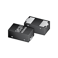
PMEG2005AELD NXP Semiconductors, PMEG2005AELD Datasheet - Page 4

PMEG2005AELD
Manufacturer Part Number
PMEG2005AELD
Description
Planar Maximum Efficiency General Application (MEGA) Schottky barrier rectifier with anintegrated guard ring for stress protection, encapsulated in a SOD882D leadless ultrasmall Surface-Mounted Device (SMD) plastic package with visible and solderable
Manufacturer
NXP Semiconductors
Datasheet
1.PMEG2005AELD.pdf
(14 pages)
NXP Semiconductors
6. Thermal characteristics
PMEG2005AELD
Product data sheet
Fig 2.
Z
(K/W)
th(j-a)
10
10
10
3
2
10
FR4 PCB, standard footprint
Transient thermal impedance from junction to ambient as a function of pulse duration; typical values
–3
duty cycle =
0.25
0.5
0.1
1
0
0.75
0.33
0.02
0.01
0.05
0.2
Table 6.
[1]
[2]
[3]
[4]
[5]
Symbol
R
R
10
th(j-a)
th(j-sp)
–2
For Schottky barrier diodes thermal runaway has to be considered, as in some applications the reverse
power losses P
Device mounted on an FR4 PCB, single-sided copper, tin-plated and standard footprint.
Device mounted on an FR4 PCB, single-sided copper, tin-plated, mounting pad for cathode 1 cm
Device mounted on a ceramic PCB, Al
Soldering point of cathode tab.
Thermal characteristics
Parameter
thermal resistance from
junction to ambient
thermal resistance from
junction to solder point
All information provided in this document is subject to legal disclaimers.
R
10
are a significant part of the total power losses.
–1
Rev. 1 — 10 May 2011
1
2
O
20 V, 0.5 A low V
3
, standard footprint.
Conditions
in free air
10
PMEG2005AELD
F
MEGA Schottky barrier rectifier
[1][2]
[1][3]
[1][4]
[5]
Min
-
-
-
-
10
2
Typ
-
-
-
-
t
p
© NXP B.V. 2011. All rights reserved.
(s)
006aac557
Max
370
190
125
50
10
3
2
.
Unit
K/W
K/W
K/W
K/W
4 of 14


