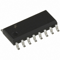
MM74HC4040M Fairchild Semiconductor, MM74HC4040M Datasheet - Page 4

MM74HC4040M
Manufacturer Part Number
MM74HC4040M
Description
IC COUNTER BINARY 12ST 16-SOIC
Manufacturer
Fairchild Semiconductor
Series
74HCr
Datasheet
1.MM74HC4040M.pdf
(9 pages)
Specifications of MM74HC4040M
Logic Type
Binary Counter
Direction
Up
Number Of Elements
1
Number Of Bits Per Element
12
Reset
Asynchronous
Count Rate
50MHz
Trigger Type
Negative Edge
Voltage - Supply
2 V ~ 6 V
Operating Temperature
-40°C ~ 85°C
Mounting Type
Surface Mount
Package / Case
16-SOIC (3.9mm Width)
Counter Type
Binary
Counting Sequence
Up
Number Of Circuits
1
Logic Family
74HC
Propagation Delay Time
210 ns, 42 ns, 36 ns
Supply Voltage (max)
6 V
Maximum Operating Temperature
+ 85 C
Minimum Operating Temperature
- 40 C
Function
Counter
Mounting Style
SMD/SMT
Operating Supply Voltage
2 V to 6 V
Lead Free Status / RoHS Status
Lead free / RoHS Compliant
Timing
-
Lead Free Status / Rohs Status
Lead free / RoHS Compliant
Available stocks
Company
Part Number
Manufacturer
Quantity
Price
Company:
Part Number:
MM74HC4040M
Manufacturer:
Fairchild Semiconductor
Quantity:
1 859
Part Number:
MM74HC4040M
Manufacturer:
FAIRCHILD/仙童
Quantity:
20 000
Company:
Part Number:
MM74HC4040MX
Manufacturer:
FAIRCHILD
Quantity:
2 826
www.fairchildsemi.com
f
t
t
t
t
t
t
t
C
C
f
t
t
t
t
MAX
PHL
PHL,
PHL
REM
W
TLH
r
MAX
PHL
PHL
REM
W
AC Electrical Characteristics
V
Note 6: Typical Propagation delay time to any output can be calculated using: t
AC Electrical Characteristics
V
Note 7: C
I
, t
PD
IN
S
Symbol
CC
CC
f
Symbol
, t
, t
, t
C
t
PLH
THL
PLH
PLH
PD
5V, T
2.0V to 6.0V, C
V
PD
CC
determines the no load dynamic power consumption, P
Maximum Operating
Frequency
Maximum Propagation
Delay Clock to Q
Maximum Propagation
Delay Between Stages
from Q
Maximum Propagation
Delay Reset to any Q
(4020 and 4040)
Minimum Reset
Removal Time
Minimum Pulse Width
Maximum
Output Rise
and Fall Time
Maximum Input Rise and
Fall Time
Power Dissipation
Capacitance (Note 7)
Maximum Input
Capacitance
f
A
I
CC
Maximum Operating Frequency
Maximum Propagation
Delay Clock to Q
Maximum Propagation
Delay Reset to any Q
Minimum Reset
Removal Time
Minimum Pulse Width
25 C, C
.
n
to Q
Parameter
L
n 1
L
50 pF, t
1
15 pF, t
Parameter
r
r
t
f
(per package)
t
f
6 ns (unless otherwise specified)
6 ns
Conditions
(Note 6)
D
C
2.0V
4.5V
6.0V
2.0V
4.5V
6.0V
2.0V
4.5V
6.0V
2.0V
4.5V
6.0V
2.0V
4.5V
6.0V
2.0V
4.5V
6.0V
2.0V
4.5V
6.0V
V
PD
CC
V
Conditions
CC
4
P
2
f
17
I
Typ
CC
10
40
50
80
21
18
80
18
15
72
24
20
30
10
55
9
5
12(N–1) ns; where N is the number of the output, Q
T
V
A
CC
, and the no load dynamic current consumption,
25 C
1000
210
125
240
100
500
400
30
35
42
36
25
21
48
41
20
16
90
16
14
75
15
13
10
6
T
A
Guaranteed Limits
Typ
1000
50
17
16
10
10
40 to 85 C T
265
156
302
126
100
500
400
24
28
53
45
31
26
60
51
25
21
20
18
95
19
16
10
5
Guaranteed
A
Limit
30
35
40
20
16
55 to 125 C
1000
313
188
358
149
120
110
500
400
20
24
63
53
38
31
72
61
50
25
24
20
22
19
10
4
W
, at V
CC
Units
MHz
ns
ns
ns
ns
5V.
Units
MHz
pF
pF
ns
ns
ns
ns
ns
ns
ns


