EPC2TI32N Altera, EPC2TI32N Datasheet - Page 10
EPC2TI32N
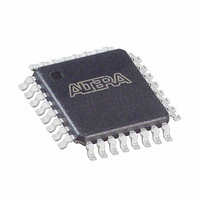
Manufacturer Part Number
EPC2TI32N
Description
IC CONFIG DEVICE 1.6MBIT 32-TQFP
Manufacturer
Altera
Series
EPCr
Datasheet
1.EPC1PC8.pdf
(26 pages)
Specifications of EPC2TI32N
Programmable Type
In System Programmable
Memory Size
1.6Mb
Voltage - Supply
3 V ~ 3.6 V, 4.5 V ~ 5.5 V
Operating Temperature
-40°C ~ 85°C
Package / Case
32-TQFP, 32-VQFP
Lead Free Status / RoHS Status
Lead free / RoHS Compliant
Other names
544-1648
Available stocks
Company
Part Number
Manufacturer
Quantity
Price
Company:

Part Number:
EPC2TI32N
Manufacturer:
ON
Quantity:
36 000
Company:
Part Number:
EPC2TI32N
Manufacturer:
ALTERA31
Quantity:
2 439
Part Number:
EPC2TI32N
Manufacturer:
ALTERA/阿尔特拉
Quantity:
20 000


4–10 Chapter 4: Configuration Devices for SRAM-Based LUT Devices Data Sheet
3.3-V or 5.0-V Operation
Configuration Handbook (Complete Two-Volume Set)
cycles after the last configuration bit was sent for CONF_DONE to reach a high state. In
this case, the configuration device pulls its OE pin low, which in turn drives the target
device’s nSTATUS pin low. Configuration automatically restarts if the Auto-restart
configuration on error option is turned on in the Quartus II software from the
General tab of the Device & Pin Options dialog box or the MAX+PLUS II software’s
Global Project Device Options dialog box (Assign menu).
In addition, if the FPGA detects a cyclical redundancy code (CRC) error in the
received data, it will flag the error by driving nSTATUS low. This low signal on
nSTATUS will drive the OE pin of the configuration device low, which will reset the
configuration device. CRC checking is performed when configuring all Altera FPGAs.
The EPC1, EPC2, and EPC 1441 configuration device may be powered at 3.3 V or
5.0 V. For each configuration device, an option must be set for 5.0-V or 3.3-V
operation.
For EPC1 and EPC1441 configuration devices, 3.3-V or 5.0-V operation is controlled
by a programming bit in the .pof. The Low-Voltage mode option in the Options tab of
the Configuration Device Options dialog box in the Quartus II software or the Use
Low-Voltage Configuration EPROM option in the Global Project Device Options
dialog box (Assign menu) in the MAX+PLUS II software sets this parameter. For
example, EPC1 devices are programmed automatically to operate in 3.3-V mode when
configuring FLEX 10KA devices, which have a V
the EPC1 device’s VCC pin is connected to a 3.3-V power supply.
For EPC2 devices, this option is set externally by the VCCSEL pin. In addition, the
EPC2 device has an externally controlled option, set by the VPPSEL pin, to adjust the
programming voltage to 5.0 V or 3.3 V. The functions of the VCCSEL and VPPSEL pins
are described below. These pins are only available in the EPC2 devices.
■
■
VCCSEL pin – For EPC2 configuration devices, 5.0-V or 3.3-V operation is
controlled by the VCCSEL option pin. The device functions in 5.0-V mode when
VCCSEL is connected to GND; the device functions in 3.3-V mode when VCCSEL is
connected to V
VPPSEL pin – The EPC2 V
EPC2 devices operating at 3.3 V, it is possible to improve in-system programming
times by setting V
to V
VPP pin. If the VPP pin is supplied by a 5.0-V supply, VPPSEL must be connected
to GND; if the VPP pin is supplied by a 3.3-V power supply, VPPSEL must be
connected to V
CC
. The EPC2 device’s VPPSEL pin must be set in accordance with the EPC2
CC
CC
.
.
PP
to 5.0 V. For all other configuration devices, V
PP
programming power pin is normally tied to V
CC
voltage of 3.3 V. In this example,
© December 2009
PP
Power and Operation
must be tied
Altera Corporation
CC
. For
Related parts for EPC2TI32N
Image
Part Number
Description
Manufacturer
Datasheet
Request
R

Part Number:
Description:
IC CONFIG DEVICE 1MBIT 8-DIP
Manufacturer:
Altera
Datasheet:

Part Number:
Description:
IC CONFIG DEVICE 1.6MBIT 20-PLCC
Manufacturer:
Altera
Datasheet:
Part Number:
Description:
IC CONFIG DEVICE 1.6MBIT 20-PLCC
Manufacturer:
Altera
Datasheet:

Part Number:
Description:
IC CONFIG DEVICE 1.6MBIT 32-TQFP
Manufacturer:
Altera
Datasheet:
Part Number:
Description:
IC CONFIG DEVICE 1.6MBIT 32-TQFP
Manufacturer:
Altera
Datasheet:
Part Number:
Description:
IC CONFIG DEVICE 1.6MBIT 20-PLCC
Manufacturer:
Altera
Datasheet:
Part Number:
Description:
IC CONFIG DEVICE 1.6MBIT 20-PLCC
Manufacturer:
Altera
Datasheet:

Part Number:
Description:
IC CONFIG DEVICE 8MBIT 100-PQFP
Manufacturer:
Altera
Datasheet:
Part Number:
Description:
IC CONFIG DEVICE 1.6MBIT 32-TQFP
Manufacturer:
Altera
Datasheet:
Part Number:
Description:
IC CONFIG DEVICE 16MBIT 100-PQFP
Manufacturer:
Altera
Datasheet:
Part Number:
Description:
IC CONFIG DEVICE 16MBIT 100-PQFP
Manufacturer:
Altera
Datasheet:
Part Number:
Description:
IC CONFIG DEVICE 16MBIT 100-PQFP
Manufacturer:
Altera
Datasheet:

Part Number:
Description:
IC CONFIG DEVICE 16MBIT 88-UBGA
Manufacturer:
Altera
Datasheet:
Part Number:
Description:
IC CONFIG DEVICE 212KBIT 20-PLCC
Manufacturer:
Altera
Datasheet:
Part Number:
Description:
IC CONFIG DEVICE 4MBIT 100-PQFP
Manufacturer:
Altera
Datasheet: