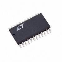
LTC1421CSW#TR Linear Technology, LTC1421CSW#TR Datasheet - Page 3

LTC1421CSW#TR
Manufacturer Part Number
LTC1421CSW#TR
Description
IC CONTROLLER HOTSWAP ADJ 24SOIC
Manufacturer
Linear Technology
Type
Hot-Swap Controllerr
Datasheet
1.LTC1421CG-2.5PBF.pdf
(24 pages)
Specifications of LTC1421CSW#TR
Applications
General Purpose
Internal Switch(s)
No
Voltage - Supply
3 V ~ 12 V
Operating Temperature
0°C ~ 70°C
Mounting Type
Surface Mount
Package / Case
24-SOIC (0.300", 7.50mm Width)
Linear Misc Type
Positive Low Voltage
Family Name
LTC1421
Package Type
SOIC W
Operating Supply Voltage (min)
3V
Operating Supply Voltage (max)
12V
Operating Temperature (min)
0C
Operating Temperature (max)
70C
Operating Temperature Classification
Commercial
Mounting
Surface Mount
Pin Count
24
Lead Free Status / RoHS Status
Contains lead / RoHS non-compliant
Lead Free Status / RoHS Status
Contains lead / RoHS non-compliant
Available stocks
Company
Part Number
Manufacturer
Quantity
Price
ELECTRICAL CHARACTERISTICS
temperature range, otherwise specifications are at T
SYMBOL
I
I
V
V
V
I
V
V
I
AC CHARACTERISTICS
t
t
t
t
t
t
t
t
t
t
t
t
Note 1: Absolute Maximum Ratings are those values beyond which the life
of a device may be impaired.
Note 2: All currents into device pins are positive; all currents out of device
pins are negative. All voltages are reference to ground unless otherwise
specified.
RAMP
CP
IN
PU
1
2
3
4
5
6
7
9
10
11
CHL
CLH
AUXVCC
IL
IH
OL
OH
V
V
GATEHI
GATELO
PARAMETER
RAMP Pin Output Current
Charge Pump Output Current
GATEHI N-Channel Gate Drive
GATELO N-Channel Gate Drive
Auxiliary V
Input Low Voltage
Input High Voltage
Input Current
Output Low Voltage
Output High Voltage
Logic Output Pull-Up Current
CON1 or CON2 to CPON
PWRGD to RESET
PWRGD to DISABLE
POR to CPON
PWRGD to RESET
POR to CPON
CON1 or CON2 to CPON
Short-Circuit Detect to FAULT
Short-Circuit Detect to CPON
POR to FAULT
Comparator High to Low
Comparator Low to High
CC
Output Voltage
CONDITIONS
Charge Pump On, V
Charge Pump On, GATEHI = 0V
GATELO = 0V
V
V
V
CON1, CON2, POR
CON1, CON2, POR
CON1, CON2, POR = GND
RESET, COMPOUT, PWRGD, DISABLE, FAULT,
I
CPON, I
DISABLE, I
CPON, I
RESET, PWRGD, FAULT = GND
Figure 1, C
Figure 1, R
Figure 1, C
Figure 1, C
Figure 1, R
Figure 1, C
Figure 1, C
Figure 1, R
V
Figure 2, C
V
Figure 2, R
COMP
R
COMP
R
O
GATEHI
GATELO
CCLO
CCLO
CCLO
L
L
= 3mA
= 10k to V
= 10k to V
A
= 25 C. V
= 5V, Unloaded
– SETLO = 0mV to 100mV
– SETLO = 0mV to 100mV
–
–
O
O
= 1.232V, 10mV Overdrive
= 1.232V, 10mV Overdrive
= 3mA
= – 1mA
V
V
The
L
L
L
L
L
L
O
L
L
L
L
OUTHI
OUTLO
= 15pF
= 10k to V
= 15pF
= 15pF
= 10k to V
= 15pF
= 15pF
= 10k to V
= 15pF
= 10k to V
= – 3mA
CCLO
CCLO
CCHI
, C
, C
denotes specifications which apply over the full operating
RAMP
L
L
= 12V, V
= 15pF
= 15pF
CCLO
CCLO
CCLO
CCLO
Note 3: After power-on reset, the V
V
Note 4: After power-on reset, the V
before the charge pump is restarted.
TRIP
, C
, C
, C
, C
0.4V
point before the charge pump is restarted.
L
L
L
L
CCLO
= 15pF
= 15pF
= 15pF
= 15pF
= 5V unless otherwise noted (Note 2).
LTC1421/LTC1421-2.5
OUTLO
OUTLO
MIN
– 30
160
140
160
140
3.4
11
10
15
15
6
2
4
and V
has to drop below the V
– 600
– 300
– 60
– 15
0.25
TYP
200
200
200
200
4.5
OUTHI
17
20
20
32
50
50
20
20
20
1
have to drop below the
MAX
1.45
– 90
240
280
240
280
0.8
0.4
0.5
1.5
23
16
16
30
30
TRIP
UNITS
point
3
ms
ms
ms
ms
ms
ms
ns
ns
ns
A
A
A
V
V
V
V
V
A
V
V
V
V
A
s
s
s
s
s


