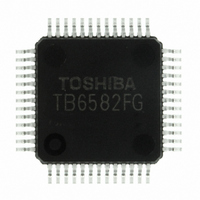
TB6582FG(O,EL) Toshiba, TB6582FG(O,EL) Datasheet - Page 12

TB6582FG(O,EL)
Manufacturer Part Number
TB6582FG(O,EL)
Description
IC BRUSHLESS MOTOR CTLR 52-QFP
Manufacturer
Toshiba
Type
3 Phase Full Wave Brushless Motor Controllerr
Datasheet
1.TB6582FGOEL.pdf
(28 pages)
Specifications of TB6582FG(O,EL)
Applications
DC Motor Controller, Brushless (BLDC), 3 Phase
Number Of Outputs
1
Voltage - Supply
6.5 V ~ 16.5 V
Operating Temperature
-30°C ~ 115°C
Mounting Type
Surface Mount
Package / Case
52-QFP
Product
Fan / Motor Controllers / Drivers
Operating Supply Voltage
15 V
Supply Current
16 mA
Mounting Style
SMD/SMT
Lead Free Status / RoHS Status
Lead free / RoHS Compliant
Current - Output
-
Voltage - Load
-
Lead Free Status / Rohs Status
Lead free / RoHS Compliant
Other names
TB6582FG(O,EL)
TB6582FGOELTR
TB6582FGOELTR
Available stocks
Company
Part Number
Manufacturer
Quantity
Price
Note 1: Since the Sys.RES input is a higher priority input, all the logic are turned off when the Sys.RES goes Low,
Note 2: : Don’t care.
4. Controls the commutation output with the input signal status and
5. Phase Current Detection Circuit
High
Low
EP
motor operation status.
The phase current detection at each phase of the coil is performed using the shunt resistor (Rf) connected
between the low-side output driver (IGBT or FET) and GND. The induced voltage at the shunt resistor is
amplified 3 times to be used as the internal signal. Since the current-voltage converted value is processed
based on 2.5 V, the maximum amplitude of shunt voltage must not exceed 0.5 V.
which puts the motor in free run mode. Thus, the above table shows the motor status when the Sys.RES
signal is High.
0 to 2.1 V
0 to 5.4 V
2.1 to
5.4 V
V
Phase current
SP
Input information to the IC
CW/CCW
I
OUT
CCW
CCW
CW
CW
Rf
V
Within the
setting
range
Out of the
GND
(V
Rf
setting
range
VM
COM
Design Specifications
)
Rotation
Amplification (×3)
Rotate
Rotate
Rotate
Rotate
speed
Stop
Stop
Phase current
detection &
of the motor
Initial state
Rotation
direction
CCW
CCW
CW
CW
12
All drive outputs: Low
All drive outputs: Low
DC excitation for startup
→ forced commutation
→ sensorless square
wave → sensorless sine
wave
Sensorless square wave
→ sensorless sine wave
Reverse rotation brake
→ DC excitation for
reverse rotation →
forced commutation →
sensorless square
wave→ sensorless sine
wave
Sensorless square wave
→ sensorless sine wave
Reverse rotation brake
→ DC excitation for
reverse rotation →
forced commutation →
sensorless square
wave→ sensorless sine
wave
All drive outputs: Low
To sample/hold unit
Control
V
V
RF
RF
IC output
= Rf × I
≤ 0.5 (V)
rotation in
rotation in
rotation in
rotation in
rotation in
rotation in
direction
direction
direction
direction
direction
direction
Forward
Reverse
Forward
Reverse
Output
OUT
CCW
CCW
CCW
OFF
OFF
Start
Start
OFF
CW
CW
CW
Preliminary
(FG, REV)
detection
Rotation
ON
ON
ON
ON
ON
ON
ON
ON
ON
TB6582FG
2007-10-18
Free run
Free run
Free run
status
Motor
Drive
Drive
Drive
Drive
Drive
Drive


