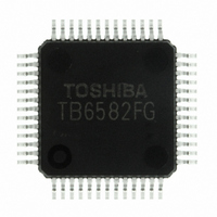
TB6582FG(O,EL) Toshiba, TB6582FG(O,EL) Datasheet - Page 9

TB6582FG(O,EL)
Manufacturer Part Number
TB6582FG(O,EL)
Description
IC BRUSHLESS MOTOR CTLR 52-QFP
Manufacturer
Toshiba
Type
3 Phase Full Wave Brushless Motor Controllerr
Datasheet
1.TB6582FGOEL.pdf
(28 pages)
Specifications of TB6582FG(O,EL)
Applications
DC Motor Controller, Brushless (BLDC), 3 Phase
Number Of Outputs
1
Voltage - Supply
6.5 V ~ 16.5 V
Operating Temperature
-30°C ~ 115°C
Mounting Type
Surface Mount
Package / Case
52-QFP
Product
Fan / Motor Controllers / Drivers
Operating Supply Voltage
15 V
Supply Current
16 mA
Mounting Style
SMD/SMT
Lead Free Status / RoHS Status
Lead free / RoHS Compliant
Current - Output
-
Voltage - Load
-
Lead Free Status / Rohs Status
Lead free / RoHS Compliant
Other names
TB6582FG(O,EL)
TB6582FGOELTR
TB6582FGOELTR
Available stocks
Company
Part Number
Manufacturer
Quantity
Price
Functional Description
PWM Duty
90%
1. Basic Operation
2. Drive Control with Operation Instruction Input (V
0
The TB6582FG is a sensorless 3-phase hall motor controller driven by the sine wave. It provides a
sensorless square-wave drive with zero-cross detection of the induced voltage, without using position
sensors, such as a Hall-effect element. It also achieves a sensorless sine-wave drive by calculating the
induced voltage waveform using the induced voltage equation.
At startup, the motor operates in sensorless square-wave mode. The operation mode switches to sensorless
sine-wave mode when the rotation speed reaches 90 rpm in the case of an 8-pole motor.
Basic Operation Flow
<Rotation Speed for Drive-Signal Switching>
Control the commutation output with V
(1)
(2)
(3)
0
*: A refresh operation is not performed.
Rotation speed is converted from the phase-current frequency Tu. When Tu reaches 6 Hz, the drive signal
is switched between square wave and sine wave.
Rotation speed: R (rpm) = 60 × Tu × (2/N)
DC excitation
Voltage instruction input: 0 V ≤ V
Disables (Low) the commutation output
Voltage instruction input: 2.1 V ≤ V
Controls the motor drive.
Voltage instruction input: 9.5 V ≤ V
Automatic lead-angle correction feature is disabled.
A mode switching occurs when V
Example) When using a 8-pole motor
(Determined by
(1)
C
IP
and R
2.1 (V)
commutation
ST
R = 60 × 6 × 2/8 = 90 (rpm)
Thus,
Forced
)
•
•
Sensorless square-wave drive: From start to 90 rpm
Sensorless sine-wave drive: 90 rpm ∼
F
ST
Design Specifications
square wave
Sensorless
SP
SP
SP
SP
SP
= 9.0 V (typ.).
< 2.1 V
input voltage.
( * )
≤ 8.5 V
≤ 11 V (Test mode)
6 Hz
5.4 (V)
(2)
9
Sensorless
sine wave
Current frequenchy
Tu = 6 Hz, N = Number of motor poles
SP
)
Preliminary
8.5 (V) 9.5 (V)
(3)
TB6582FG
11 (V)
2007-10-18
V
SP


