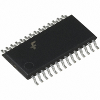
FAN5094MTCX Fairchild Semiconductor, FAN5094MTCX Datasheet - Page 2

FAN5094MTCX
Manufacturer Part Number
FAN5094MTCX
Description
IC CTRLR DC/DC SYNC BUCK 28TSSOP
Manufacturer
Fairchild Semiconductor
Datasheet
1.FAN5094MTCX.pdf
(22 pages)
Specifications of FAN5094MTCX
Applications
Controller, Intel Pentium® IV
Voltage - Input
12V
Number Of Outputs
1
Voltage - Output
1.1 ~ 1.85 V
Operating Temperature
0°C ~ 70°C
Mounting Type
Surface Mount
Package / Case
28-TSSOP
Output Voltage
1.85 V
Output Current
60 A
Mounting Style
SMD/SMT
Maximum Operating Temperature
+ 70 C
Minimum Operating Temperature
0 C
Lead Free Status / RoHS Status
Lead free / RoHS Compliant
Other names
FAN5094MTCXTR
FAN5094MTCX_NL
FAN5094MTCX_NLTR
FAN5094MTCX_NLTR
FAN5094MTCX_NL
FAN5094MTCX_NLTR
FAN5094MTCX_NLTR
FAN5094
Pin Assignments
Pin Definitions
2
Pin Number
1-5
10
11
12
13
14
15
16
17
18
6
7
8
9
VID0-4
CLK
BYPASS
AGND
LDRVB
GNDB
ISNSB
SWB
HDRVB
BOOTB
BOOTA
HDRVA
SWA
ISNSA
Pin Name
BYPASS
HDRVB
BOOTB
LDRVB
ISNSB
GNDB
AGND
SWB
VID0
VID1
VID2
VID3
VID4
CLK
Voltage Identification Code Inputs. These open collector/TTL compatible
inputs will program the output voltage over the ranges specified in Table 1.
Clock. When PHASE is high, this pin puts out a clock signal synchronized
180 out of phase with the internal master clock. When PHASE is low, this pin
is an input for a synchronizing clock signal.
5V Rail. Bypass this pin with a 0.1 F ceramic capacitor to AGND.
Analog Ground. Return path for low power analog circuitry. This pin should
be connected to a low impedance system ground plane to minimize ground
loops.
Low Side FET Driver for B. Connect this pin to the gate of an N-channel
MOSFET for synchronous operation. The trace from this pin to the MOSFET
gate should be <0.5”.
Ground B. Ground-side current sense pin. Connect directly to low-side
MOSFET source, or to sense resistor ground.
Current Sense B. Sensor side of current sense. Attach to low-side MOSFET
drain, or to source side of sense resistor.
High side driver source and low side driver drain switching node B. Gate
drive return for high side MOSFET, and negative input for low-side MOSFET
current sense.
High Side FET Driver B. Connect this pin to the gate of an N-channel
MOSFET. The trace from this pin to the MOSFET gate should be <0.5”.
Bootstrap B. Input supply for high-side MOSFET.
Bootstrap A. Input supply for high-side MOSFET.
High Side FET Driver A. Connect this pin to the gate of an N-channel
MOSFET. The trace from this pin to the MOSFET gate should be <0.5”.
High side driver source and low side driver drain switching node A. Gate
drive return for high side MOSFET, and negative input for low-side MOSFET
current sense.
Current Sense A. Sensor side of current sense. Attach to low-side MOSFET
drain, or to source side of sense resistor.
1
2
3
4
5
6
7
8
9
10
11
12
13
14
FAN5094
Pin Function Description
28
27
26
25
24
23
22
21
20
19
18
17
16
15
VFB
RT
ENABLE/SS
DROOP/E*
ISHR
PHASE
PWRGD
VCC
LDRVA
GNDA
ISNSA
SWA
HDRVA
BOOTA
PRODUCT SPECIFICATION
REV. 1.0.2 5/13/02


