MT9VDDF6472Y-335F1 Micron Technology Inc, MT9VDDF6472Y-335F1 Datasheet - Page 18
MT9VDDF6472Y-335F1
Manufacturer Part Number
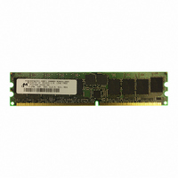
MT9VDDF6472Y-335F1
Description
MODULE DDR SDRAM 512MB 184-DIMM
Manufacturer
Micron Technology Inc
Specifications of MT9VDDF6472Y-335F1
Memory Type
DDR SDRAM
Memory Size
512MB
Speed
167MHz
Package / Case
184-DIMM
Main Category
DRAM Module
Sub-category
DDR SDRAM
Module Type
184RDIMM
Device Core Size
72b
Organization
64Mx72
Total Density
512MByte
Chip Density
512Mb
Maximum Clock Rate
333MHz
Operating Supply Voltage (typ)
2.5V
Operating Current
1.575A
Number Of Elements
9
Operating Supply Voltage (max)
2.7V
Operating Supply Voltage (min)
2.3V
Operating Temp Range
0C to 70C
Operating Temperature Classification
Commercial
Pin Count
184
Mounting
Socket
Lead Free Status / RoHS Status
Lead free / RoHS Compliant
Other names
557-1293
MT9VDDF6472Y-335F1
MT9VDDF6472Y-335F1


Table 15: DDR SDRAM Component Electrical Characteristics and Recommended AC
Notes: 1–5, 8, 10, 12; notes appear on pages 20–23; 0°C
Table 16: DDR SDRAM Component Electrical Characteristics and Recommended AC
Notes: 1–5, 8, 10, 12; notes appear on pages 20–23; 0°C
pdf: 09005aef80e119b2, source: 09005aef807d56a1
DDF9C32_64x72G.fm - Rev. B 9/04 EN
AC CHARACTERISTICS
PARAMETER
Access window of DQs from CK/CK#
CK high-level width
CK low-level width
Clock cycle time
DQ and DM input hold time relative to DQS
DQ and DM input setup time relative to DQS
DQ and DM input pulse width (for each input)
Access window of DQS from CK/CK#
DQS input high pulse width
DQS input low pulse width
DQS-DQ skew, DQS to last DQ valid, per group, per access
Write command to first DQS latching transition
DQS falling edge to CK rising - setup time
DQS falling edge from CK rising - hold time
Half clock period
Data-out high-impedance window from CK/CK#
Data-out low-impedance window from CK/CK#
Address and control input hold time (fast slew rate)
Address and control input setup time (fast slew rate)
AC CHARACTERISTICS
PARAMETER
DQS read preamble
DQS read postamble
ACTIVE bank a to ACTIVE bank b command
DQS write preamble
DQS write preamble setup time
DQS write postamble
Write recovery time
Internal WRITE to READ command delay
Data valid output window
REFRESH to REFRESH command interval
Average periodic refresh interval
Terminating voltage delay to V
Exit SELF REFRESH to non-READ command
Exit SELF REFRESH to READ command
Operating Conditions (-335, -262) (Continued)
Operating Conditions (-26A, -265, -202)
DD
CL = 2.5
CL = 2
T
T
A
A
18
SYMBOL MIN
+70°C; V
+70°C; V
t
SYMBOL MIN
t
WPRES
t
t
t
t
t
t
t
t
t
WPRE
WPST
t
t
t
XSNR
XSRD
t
t
t
DQSCK
RPRE
RPST
t
REFC
CK (2.5)
t
t
t
WTR
RRD
REFI
VTD
CK (2)
DQSH
DQSQ
DIPW
t
WR
DQSL
DQSS
na
t
t
t
t
DSH
t
t
t
t
t
DSS
t
t
DH
AC
CH
HP
HZ
IH
DS
CL
LZ
IS
F
F
256MB, 512MB (x72, ECC, SR)
DD
DD
Micron Technology, Inc., reserves the right to change products or specifications without notice.
184-PIN DDR SDRAM RDIMM
0.25
200
-0.75
7.5/10
-0.75
-0.75
= V
= V
0.9
0.4
0.4
0.45
0.45
1.75
0.35
0.35
0.75
0.90
0.90
12
15
75
t
7.5
0.5
0.5
0.2
0.2
0
1
0
QH -
-26A/-265
t
DD
DD
CH,
-335
Q = +2.5V ±0.2V
Q = +2.5V ±0.2V
t
DQSQ
MAX
+0.75
+0.75
t
+0.75
MAX
CL
0.55
0.55
1.25
70.3
0.5
0.6
0.6
13
13
1.1
7.8
MIN
0.45
0.45
0.35
0.35
0.75
-0.8
-0.8
-0.8
0.6
0.6
0.2
0.2
1.1
1.1
MIN
10
0.25
200
8
2
0.9
0.4
0.4
t
12
15
75
0
1
QH -
0
t
CH,
©2004 Micron Technology, Inc. All rights reserved.
-202
-262
t
MAX
DQSQ
t
+0.8
0.55
0.55
+0.8
1.25
+0.8
MAX
CL
0.6
70.3
13
13
1.1
0.6
0.6
7.8
UNITS NOTES
UNITS NOTES
t
t
t
t
t
t
t
t
t
t
t
t
t
ns
ns
ns
ns
µs
µs
ns
ns
ns
CK
CK
ns
ns
ns
ns
ns
ns
CK
CK
ns
CK
CK
CK
ns
ns
ns
ns
ns
CK
CK
CK
CK
CK
CK
18, 19
40, 46
40, 46
23, 27
23, 27
22, 23
16, 37
16, 37
38
38
17
22
21
21
26
26
27
30
12
12
Related parts for MT9VDDF6472Y-335F1
Image
Part Number
Description
Manufacturer
Datasheet
Request
R

Part Number:
Description:
IC SDRAM 64MBIT 133MHZ 54TSOP
Manufacturer:
Micron Technology Inc
Datasheet:

Part Number:
Description:
IC SDRAM 64MBIT 5.5NS 86TSOP
Manufacturer:
Micron Technology Inc
Datasheet:
Part Number:
Description:
IC SDRAM 64MBIT 200MHZ 86TSOP
Manufacturer:
Micron Technology Inc
Datasheet:
Part Number:
Description:
IC SDRAM 64MBIT 133MHZ 54TSOP
Manufacturer:
Micron Technology Inc
Datasheet:
Part Number:
Description:
IC SDRAM 128MBIT 133MHZ 54TSOP
Manufacturer:
Micron Technology Inc
Datasheet:

Part Number:
Description:
IC SDRAM 256MBIT 133MHZ 90VFBGA
Manufacturer:
Micron Technology Inc
Datasheet:
Part Number:
Description:
IC SDRAM 128MBIT 133MHZ 54TSOP
Manufacturer:
Micron Technology Inc
Datasheet:
Part Number:
Description:
IC SDRAM 256MBIT 133MHZ 54TSOP
Manufacturer:
Micron Technology Inc
Datasheet:

Part Number:
Description:
IC DDR SDRAM 512MBIT 6NS 66TSOP
Manufacturer:
Micron Technology Inc
Datasheet:
Part Number:
Description:
IC SDRAM 128MBIT 167MHZ 86TSOP
Manufacturer:
Micron Technology Inc
Datasheet:
Part Number:
Description:
IC SDRAM 128MBIT 143MHZ 86TSOP
Manufacturer:
Micron Technology Inc
Datasheet:

Part Number:
Description:
SDRAM 256M-BIT 1.8V 54-PIN VFBGA
Manufacturer:
Micron Technology Inc
Datasheet:
Part Number:
Description:
IC SDRAM 128MBIT 143MHZ 86TSOP
Manufacturer:
Micron Technology Inc
Datasheet:

Part Number:
Description:
IC SDRAM 128MBIT 125MHZ 54VFBGA
Manufacturer:
Micron Technology Inc
Datasheet:
Part Number:
Description:
IC SDRAM 128MBIT 125MHZ 54VFBGA
Manufacturer:
Micron Technology Inc
Datasheet: